This thread has been locked.

If you have a related question, please click the "Ask a related question" button in the top right corner. The newly created question will be automatically linked to this question.

LM74800EVM-CD: LM74800EVM-CD

Part Number: LM74800EVM-CD
Other Parts Discussed in Thread: LM74800-Q1

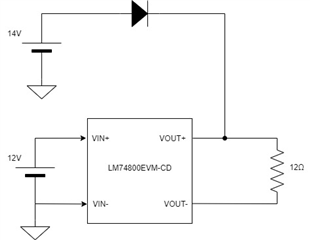
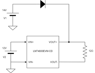
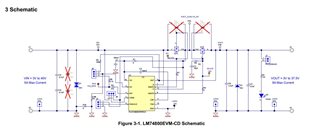
I am testing the functionality of the LM74800 driver using the LM74800EVM-CD evaluation board. My setup has the jump inserted in:

J5 -> 1-2 Enables by connecting to VIN

J6 -> 2-3 OVP set to Input OVP Cutoff at 37.5 V

J7 -> Enables LED indication for output

J8 -> 2-3 Input Voltage Sense directly on input supply

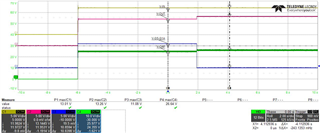
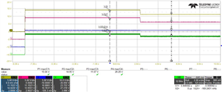
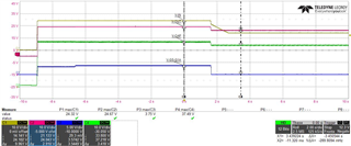
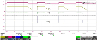
with this setup when VOUT> VIN the driver turns off the MOSFET Q1A and blocks the reverse current. I tried replacing the LM74800DRRRQ1 driver with the LM74801QDRRRQ1 driver in the evaluation board.  With the LM74801 driver when the output VOUT> VIN the driver does not turn off the MOSFET Q1A and the reverse current is not blocked.  The jumpers setup remained the same.  

I don't understand why it doesn't work properly. In the datasheet it seems the only difference is: LM74800-Q1 employs reverse current blocking using linear regulation and comparator scheme vs. LM74801-Q1 which supports comparator based scheme.

Thank you for the support.

Regards.

Federico

  • Hi Federico,

    Yes, the only difference between LM74801-Q1 and LM74800-Q1 is that the LM74801-Q1 has comparator only based gate turn OFF for reverse current while LM74800-Q1 has Linear gate regulation + comparator based scheme.

    For LM74801-Q1 to turn OFF the gate, the voltage difference between Vout and Vin should be greater than V(AC_REV) which is 4.5mV.

    May I know how are you testing the condition to enforce Vout > Vin ? If the input power supply is just unplugged/removed without discharging the Vin , then  there could be small amount of current flow from Vout to Vin which is small enough (causing a voltage drop across OUT-IN less than 4.5mV ) charging the input caps and is undetected by the LM74801-Q1. Can you try discharging Vin with a resistive load and check again ?

  • Hi Praveen,

    Thank you for your answer.

    I connected the evaluation board as shown in the following diagram:

    with the LM74800-Q1 driver in this condition the MOSFET Q1A turns off and blocks the reverse current.

    In the same configuration with the LM74801-Q1 driver, the Q1A MOSFET remains on in full conduction.

    V (AC_REV) >> 4.5mV and the input power supply to the evaluation board is never disconnected. I also tried to connect a 100kΩ resistor in parallel to the 12V power supply, but it doesn't change, the MOSFET Q1A is always on.

    Thank you for your support.

    Best regards.

    Federico 

  • Hi Federico,

    When there is 13.3V (14V-Diode Drop) at output and 12V at the input of LM74800EVM-CD then the LM74801-Q1 device should definitely turn OFF the gate. The only possible reasons I could think of are damaged IC / improper soldering. Have you tried soldering and testing with a new LM74801-Q1 IC. Have you made any other changes on the EVM other than replacing the LM74800-Q1 with LM74801-Q1 ?

  • Hi Praveen, 

    I tried to replace the LM74801-Q1 driver. I investigated the diversity of functioning more thoroughly: 

    1. if I turn on the power supply V1 set with Vout = 12V and then turn on the power supply V2 with Vout = 14V then LM74801-Q1 turns off the MOSFET Q1A (Ideal diode)
    2. if from the condition described in point 1 I raise the voltage of V2 = 15V, LM74801-Q1 turns on the MOSFET Q1A and all the power supplied is supplied by V2,
    3. if from the condition described in point 2 I lower the voltage V2 = 12V the LM74801-Q1 driver DOES NOT turn off the MOSFET Q1A but remains in conduction.
    4. If from the condition described in point 3 I turn off the power supply V2, the evaluation board remains powered by V1 and the MOSFET Q1A remains on in conduction.

    If I execute the same sequence with the LM74800-Q1 driver, this works as a diode, that is when I am in condition 3, with V1 = 14V and V2 = 15V and I lower the voltage of V2 = 12V the LM74800-Q1 driver turns OFF the Q1A MOSFET. This is the big difference between LM74800 and LM74801. 

    Is it correct that there is this difference in operation between the two drivers?

    Thank you.

    Best regards.

    Federico 

  • Hi Federico,

    Thanks for providing more information. Can you verify the point 1 again. When V1=12V and V2 = 14V, the LM74801-Q1 will turn 'ON' the MOSFET Q1A.

    From you description of I understand that initially when V1 = 12V, V2 = 15V, the LM74801-Q1 has turned ON Q1A but when V2 is dropped from 15V to 12V, the Q1A is not turned OFF by LM74801-Q1.  Is my understanding correct ? In this condition as V1=V2 = 12V, the LM74801-Q1 will not turn OFF Q1A. have you tried dropping V2 voltage from 15V to 11V ?

  • Hello Praveen, 

    the operation of the LM74801-Q1 driver depends on the switching on and regulation sequence of power supplies V1 and V2.

    • Test-1: Switching on of V2 = 12V and then switching on of V1 = 14V -> LM74801-Q1 turns OFF the Q1A MOSFET (OK it's like a diode )
    • Test-2: Switching on of V1 = 12V and then switching on of V2 = 14V -> LM74801-Q1 turns ON the Q1A MOSFET (OK it's like a diode )
    • Test-3: Switching on of V1 = 12V and then switching on of V2 = 14V -> LM74801-Q1 turns ON the Q1A MOSFET, then if I lower the voltage of V2 = 14V and bring it to V2 = 10V or V2 = 8V the LM74801-Q1 driver no longer turns off the Q1A MOSFET, while the LM74800-Q1 driver turns it off correctly as if it were a diode. If in this condition I turn off the power supply V2 the LM74801-Q1 driver remains powered through the power supply V1 and the gate of the MOSFET Q1A is always high keeping the MOSFET Q1A on. 

    From you description of I understand that initially when V1 = 12V, V2 = 15V, the LM74801-Q1 has turned ON Q1A but when V2 is dropped from 15V to 12V, the Q1A is not turned OFF by LM74801-Q1.  Is my understanding correct ? In this condition as V1=V2 = 12V, the LM74801-Q1 will not turn OFF Q1A. have you tried dropping V2 voltage from 15V to 11V ? -> Yes correct, you got it right Praveen. Yes I tried to lower the voltage of V2 down to zero volts but the LM74801-Q1 driver never turns off the MOAFET Q1A. This is the anomaly instead in this same condition the LM74800-Q1 driver works correctly.

    Thank you so much Praveen for your support.

    Best regards.

    Federico 

  • Hi Federico,

    I understand the problem clearly. Please fin my explanation below,

    LM74800-Q1 has linear gate control technique. With this control technique, the Gate voltage is reduced (to increase MOSFET resistance) as  the load current reduces so as to maintain the voltage across FET source-drain at V(AC_REG). This way as the load current reduces and tries to -ve, the Gate is completely turned OFF allowing 0A reverse current. 

    On the other hand LM74801-Q1 has comparator only based reverse current blocking and the gate voltage is always high (as long as load current is +ve) irrespective of the load current. This means that there needs to be some reverse current flow (=V(AC_REV)/RDS(ON)) for the controller to detect and turn OFF the FETs. In the test case where you see unexpected behavior, what is happening is that a reverse current of magnitude less than the detectable threshold is flowing and charging the V2 (from VOUT) to a value equal to VOUT. In other words, the reverse current flow is able to charge the V2 to VOUT voltage without LM74801-Q1 detecting reverse current. We can make LM74801-Q1 detect reverse current and turn OFF by one of the following methods,

    1. Increase input capacitance.
      1. Higher the input cap, more the current required from output to charge it to VOUT level and this can help detect reverse.
    2. Use a FET with Higher RDS(ON).
      1. This will help increase the voltage across the FET for a given reverse current and leads to early detection and FET turn OFF by the controller.
    3. Turn OFF/ Ramp down V2 at higher slew rate. 
  • Hi Praveen, 

    Thanks for the explanation. I have increased the input capacity and performed the following test: 

    Switching on of V1 = 12V and then switching on of V2 = 14V -> LM74801-Q1 turns ON the Q1A MOSFET -> then I quickly lowered (like a step) the voltage

    V2 = 04V the LM74801-Q1 driver doesn't turns off the Q1A MOSFET, the reverse current is 50mA. 

    In this configuration where V1 = 12V and V2 is lowered even to zero volts, the LM74801-Q1 driver never turns off the Q1A MOSFET. This means that it doesn't work as an ideal diode. Are you sure this is not a chip bug?

    Thank you.

    Best regards.

    Federico 

  • Hi Federico,

    When you V2 power supply is lowered to 4V from 14V, what is the voltage measured at the input of LM74801-Q1 ?

    **The voltage at input of LM74801-Q1 can be different from the voltage set on the power supply (V2) if the power supply does not allow reverse current to flow into it.

    Can you share waveforms with the following signals captured - voltage at input of LM74801-Q1, output of LM74801-Q1, DGate, VCAP

  • Hi Praveen, 

    Test-1: Switching on of V2 = 12V and then switching on of V1 = 14V -> LM74801-Q1 turns OFF the Q1A MOSFET

    Test-2: Switching on of V2 = 14V and then switching on of V1 = 12V -> LM74801-Q1 turns ON the Q1A MOSFET -> then I quickly lowered (like a step) the voltage V2 = 04V the LM74801-Q1 driver doesn't turns off the Q1A MOSFET:

    I soldered the LM74800-Q1 chip in my application board and performed test-2 (in my application I have an undervoltage threshold of 20V so I raised the voltage of V1 and V2).

    Switching on of V2 = 24V and then switching on of V1 = 22V -> LM74800-Q1 turns ON the MOSFET driven by DGATE (ideal diode) -> then I quickly lowered (like a step) the voltage V2 = 14V the LM74800-Q1 turns off the MOSFET by blocking the reverse current 

    A sequence with: V1 = 22V constant and V1 = 24V -> V2 = 14V -> V2 = 24V ...

    LM74800-Q1 driver works fine.

    I can't find this part number distributed in the online catalogs, Could you get me 5 pieces of this part number to test my application? 

    Thank you.

    Best regards.

    Federico 

  • Hi Federico,

    From your test results of Test 2 with LM74800-Q1 and LM74801-Q1, you can clearly see that the V2 is getting charged to Vout in case of LM74801-Q1 where as V2 is dropping below Vout. This is in line with my explanation above - the reverse current flow from OUT to V2 is not high enough to be detectable by the LM74801-Q1 before V2 is charged = Vout voltage. Also, the power supply on V2 is not sinking any current.

    Unfortunately,  I will not be able to help you with LM74800-Q1 samples if they are not available on TI.com . Do you have any TI field team supporting you ?

  • Hi Praveen,

    the explanation is clear. How many mA of reverse current does it take for the LM74801-Q1 driver to turn off the Q1A MOSFET? 

    I have measured a current of 50mA of reverse current and the driver still does not detect that it is in reverse bias.

    I understand how it works, but it's a bit strange because no real diode admits a reverse current of greater than 50mA in normal operation, and I thought this driver was more accurate. 

    Thank you.

    Best regards.

    Federico 

  • Hi Federico,

    LM74801-Q1 requires a voltage difference between C-A pins to be > V(AC_REV) to detect a reverse current and turn OFF the FET.

    So, the amount of revere current required =V(AC_REV)/RDS(ON)

    Considering a FET with RDS(ON) of  3mohms, the reverse current required would be = 4.5mV/3mohms = 1.5A. 

    For more understanding on this topic, please refer to section, '6.1 Linear Regulation Control Vs Hysteretic ON/OFF Control' of the Basics of Ideal Diodes Application note.

  • Hi Praveen 

    ok thank you for your support.

    Best regards.

    Federico