This thread has been locked.

If you have a related question, please click the "Ask a related question" button in the top right corner. The newly created question will be automatically linked to this question.

LM43603-Q1: Using LM43603-Q1 as an alternate to LM46002PWPT. We are having power supply start up issue

Part Number: LM43603-Q1
Other Parts Discussed in Thread: LM43603, LM46002

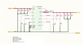
We are having startup issue with using an LM43603 rather than a LM46002.   Schematic below. 

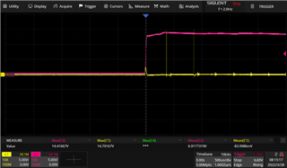
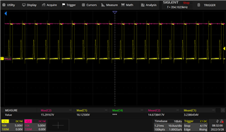
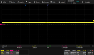
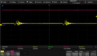
When the supply has around 6V to 8V at the input the output ripple is around 400mV.  When the input voltage goes higher the ripple goes away.

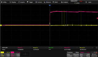
If we apply 10-15 to the input sometimes the output will not come up at all.

Any suggestions would be appreciated, we are in a big hurry to ship product.

  • Hello

    Please be sure that you use the Webench tool to design your application with the LM43603 to ensure that all of the component values are correct.

    What is your input voltage range and load current ??

    The excessive ripple on the output at low input voltages could indicate drop-out mode.

    Please provide waveforms of the input voltage, SW node voltage and output voltage for each of the issues that you have encountered, as well as for normal operation.

    Also, if you have a current probe, please provide the inductor current waveform.

    The inductor appears to be somewhat large and the output capacitor bank on the small side.

    Your input capacitors also seem a little on the light side.

    Thanks

  • Frank,

    Here is some more information about the problems we are seeing:

    We have two of these chips per board, one outputting 3.3V, one outputting 5V.

    Input voltage is 15V.

    If we immediately apply 15V to the board, neither of the power supplies turn on. Here are the scope images showing startup:

    5V supply: C2 (pink) is input voltage, C1 (yellow) is SW node

    3.3V supply

    The same happens for any input voltage over 5.5V.

    However, if we slowly ramp up the input voltage to 15V starting from about 3V, the 3.3V supply works fine. Here is what the SW node looks like in that case:

    Doing the same for the 5V does not work. Once the input voltage gets above 5V (7.5V in image), the SW node stays at about 1.75V, with no switching.

    Once the input voltage gets to about 12V, we start seeing switching, but the output voltage is still only at 1.75V.

    The load current for the 5V supply is pretty low, approximately 60mA. When we add a 20 ohm resistor from 5V to common, we are able to increase the supply voltage up to 15V and the 5V supply works as intended. SW node for this shown below.

    Adding this load resistor does not help with the issue of immediately applying 15V to the input. The waveform for each supply's SW node still looks identical to the first and second images.

    Hopefully this information helps to diagnose the problem.

  • Hello

    Please double check the component values to be sure they are compatible between 36V and 60V devices.

    Your input voltage slew rate does seem rather high.

    Can you probe the voltage on the VCC pin of the 5V design for the conditions you show above.

    The voltage rating of your output capacitors is too small for a 5Vout.  The ceramic capacitors will de-rate with DC bias.

    Try to disconnect the EN input from VIN and start-up using the EN input, with 15V on VIN.

    Thanks

  • Hi,

    There are some mismatches between the recommended component values and what we have, like you said in your first reply. We've tried reducing the inductor value and increasing the output capacitor values with no success. Things like the bootstrap capacitor, switching frequency resistor, VCC cap, etc. stay the same between the two parts.

    Here is the waveform of VCC (yellow) and Vin (Pink) with an additional load hooked up, so the 5V output is working properly.

    Here is the waveform of VCC and Vin without the additional load hooked up, so the 5V supply is sitting at about 1.75V.

    It looks like VCC is dropping out regularly. Any idea of what could be causing this?

    We would rather not disconnect the EN pin as we're worried we might damage the part. 

    Thank you for noting the issue with the output capacitor rating. They don't seem to be failing when the 5V supply is working correctly so I don't believe they are the problem here, but they should be replaced with higher rated parts.

  • Hello

    Check both the VCC and BOOT capacitor and connections to be sure they are soldered down and of the correct value

    and the capacitors are not damaged.

    Thanks

  • Frank,

    The VCC caps were indeed bad! Both power supplies are working great after replacing those.

  • Hello

    Good news.  Sorry it took so long to find root cause.

    Thanks