This thread has been locked.

If you have a related question, please click the "Ask a related question" button in the top right corner. The newly created question will be automatically linked to this question.

UCC27517: PCB layout

Part Number: UCC27517

Hi Team,

Could you please help me with below questions? Thanks.

1,When doing single-point grounding, which point should be the GROUND? I think using the source of the MOSFET as the ground point can reduce the area of ​​the driving loop. Any comments here?
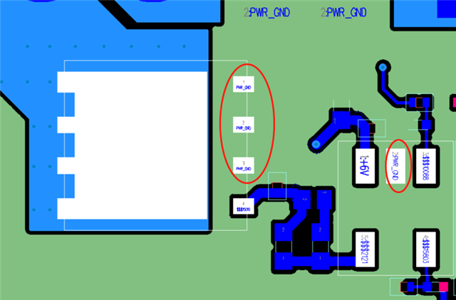
2,Figure 1 is the recommended layout from datasheet. The customer does not have the line marked by the red note, but uses a whole piece of copper to connect, as shown in Figure 2. Will this be a problem?

Fig.1
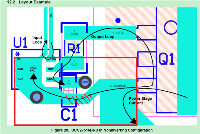
Fig.2
Best regards,

Hailiang

  • Hi Ray,

    Thank you for reaching out! 

    As far as your first question goes, I would also recommend that you use the source of the MOSFET as your ground point as this will help reduce the area of the driving loop as shown in the example layout provided in the datasheet.

    For your second question, I do not believe that using a whole piece of copper should be an issue. However it should be noted that high current on the copper plane could result in noise seen on the input pin trace.

    Thank you,

    Kevin