This thread has been locked.

If you have a related question, please click the "Ask a related question" button in the top right corner. The newly created question will be automatically linked to this question.

BQ20Z95: Unable to match PEC

Part Number: BQ20Z95

Hi Experts,

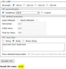
A customer is using BQ20Z95 via I2C communication and was unable to match PEC. The PEC they received does not match with the computed PEC. Through I2C they are reading 3 bytes instead of 2 bytes for PEC, 

Can you confirm if this is correct? What could be the problem with this?

Thanks in advance.

Regards,

Marvin

  • Hello Marvin,

    Can you share a logic analyzer capture of the issue they're running into?

    Sincerely,

    Wyatt Keller

  • Hi Wyatt,

    The customer currently do not have logic analyzer. so they share the protocol they're working on. Kindly refer below:

    Pull up resistors : 4.7 k ohm resistors (both CLOCK and DATA lines).

    Communication Frequency : 100 KHZ

    I2C protocol:
    1. When we are trying to read all the registers/commands from 1 to 26 regarding battery data one by one (without PEC), we are able to read correct data with no issue.

    2.When we are trying to read all the registers/commands from 1 to 26 regarding battery data one by one (with PEC), we are able to read data correctly but received PEC is not matching as per CRC polynomial calculations.

    Pls look into the example below
    Data -- 0x16, 0x01, 0x17, 0xE8, 0x03 --- PEC received is 0x56 instead of 0xD9
    Data -- 0x16, 0x01, 0x17, 0xD0, 0x07 --- PEC is 0x1B instead of 0x6D

    I hope this helps. Please let me know if you need more information.

    Regards,

    Marvin

  • Hello Marvin,

    Which commands are they trying to use? I want to make sure I understand what they're trying to implement.

    The PEC byte is a combination of the whole packet, not just the data sent or received.

    Sincerely,

    Wyatt Keller

  • Hi Wyatt,

    Here is the customer response:

    "Yes we do understand that PEC byte is combination of the whole packet of 5 bytes.
    As in the screenshot taken from bq2060 we requested remaining capacity whose command is 0x16 and reply packet is

    0x16, 0x01, 0x17, 0xE8, 0x03 --- PEC received is 0x56 instead of 0xD9"

    I hope this helps.

    Regards,

    Marvin

  • Hello Marvin,

    I'm not sure if they are implementing the PEC calculation correctly. I would need to see the full transaction using a logic analyzer to confirm.

    Remaining Capacity is command 0x0F, so I'm not sure what they are sending and receiving which is important for the calculation of a checksum.

    You can use the calculator here: http://www.sunshine2k.de/coding/javascript/crc/crc_js.html

    And guide here: https://www.ti.com/lit/pdf/slua475

    From what I can tell they are not using the whole packet - including the device address, but I cannot confirm this with the data provided.

    Sincerely,

    Wyatt Keller

  • Hi Wyatt,

    Thank you for the response. The customer is still unable to produce a capture of the logic analyzer instead, they provided the information below:


    Pls confirm whether through I2C shall we receive PEC is we read 3 bytes?

    Following is what we followed

    Battery address write is 0x16
    command is 0x01 (RemainingCapacityAlarm() )
    Battery address read 0x17
    Data is 0x03E8 ( 1000 )

    PEC received is 0x56

    PEC calculated is 0xD9

    Will this help?

    Regards,

    Marvin

  • Hello Marvin,

    I'm not sure what they mean by the receive PEC we read 3 bytes, they will need to read 3 bytes since the gauge will send the PEC byte along with the 2 bytes for remaining capacity alarm.

    When I do the PEC calculation on the data sent I get a different value than both the ones calculated by the gauge and the customer.

    This is why I would like to see the actual transmission of data if possible. They can always disable PEC if they do not want the checksum.

    Sincerely,

    Wyatt Keller

  • Hello wyatt,

    Attached is the oscilloscope waveform when we have read design voltage related information through I2C communication.

    ADDRESS with write  0x16

    COMMAND 0x19

    ADDRESS with read 0x17

    BYTE1 0x40

    BYTE2 0x38

    PEC received is 0x47

    but calculated is 0xFF

    when we try to read data by sending sequence of read commands from SMbus we are getting data as 't','e','x','a','s',' ','i','n','s','t','.'

    Can you please confirm what could be the problem

    Thanks in advance,

    Best Regards,

    Venkata praveen

  • Hello Venkata,

    You will need to send a repeated start when doing the read. Based on the conversation so far, I think you are doing a stop/start instead of repeated start before address 0x17 byte. The oscilloscope capture seems to indicate the same but it is not high enough resolution to tell for sure.