This thread has been locked.

If you have a related question, please click the "Ask a related question" button in the top right corner. The newly created question will be automatically linked to this question.

TPS2660: Watchdog Output Delay to SHDN Pin of TPS2660 -> EN Pin of TPS25974

Part Number: TPS2660

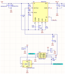
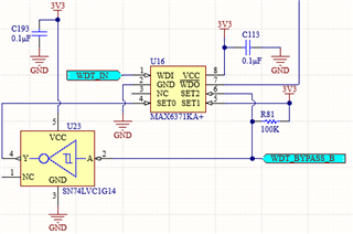
So I have a circuit here that utilizes a watchdog output assertion/deassertion for the SHDN pin of the TPS2660. I believe the delay of the watchdog output is about τ = 4.7uF*1MOhm [internal pullup of SHDN] = 4.7s(?), with a negligible difference with R117 (used for current-limiting). The timer is MAX6371KA+, and the WDO is an Open-Drain Output.

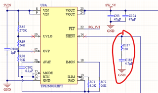
I would like to transfer this design to the TPS25974, due to parts availability. I've nailed down most other functionalities of e-Fuse, but the TPS25974 does not have a SHDN pin, so I am stuck with having to use the EN pin for the TPS25974. Does C185 need to be changed in the updated schematic (below) to take into account the Thevenin resistance network of IN/UVLO/OVLO? My ex-coworker had designed the delay, and I'm not sure if the delay calculation is truly 4.7s. Please let me know if I unclear about any details.


  • Hi Richard,

    Welcome to E2E!

    The delay is nothing but the time to reach EN threshold with the RC time constant. R being the effective resistance charging 4.7uF capacitor. I think, with the present values you get a delay of 1 sec and you have to play with R or C to meet your requirement.

    Best Regards,

    Rakesh

  • Hi Rakesh, a little unrelated from the original question, but if I tie PGTH to the output directly with just a series resistor, will PG be high all the time, unless the input hits UVLO/OVP limit?

  • Hi Richard,

    To which device, you are referring to ?

    Best Regards,

    Rakesh

  • Hi Rakesh,

    I am referring to the TPS25974.

    Also, going back to the original question, do you agree that the RC constant in the first image with the TPS26600 is ~ 4.7 sec (because of the 1Meg internal pull-up and 4.7uF cap and negligible R117)? I'm trying to pick up the pieces of this design 

  • Hi Richard,

    1. Regarding RC you have to play with RC values on prototype board and decide final values based on delay. Also one thing to get delay capacitor should be tied directly to the EN pin and resistor should be in series path like this:

    2. Please have a look at this table to see when PG can go low:

    Regards

    Kunal Goel

  • Hi Kunal, regarding your first point/image, how is that different than what is depicted in the schematic? My intention is that the pull-up resistor in your graphic is a Thevenin equivalent resistance of R65/69/70 [basically it would be 453K || (24K+133K)]. The 330Ohm resistor is just there to make sure that when the watchdog drives the reset low, the capacitor doesn't get discharged too quickly. The original pull-up resistor in TPS26600 is the 1Meg internal pullup of SHDN pin.

  • Hi Richard,

    Yeah, it is same implementation like what I depicted. Just want to mention that Thevenin theorem may not be valid with active components in circuit so thevenin resistance may not be exactly what you are calculating but method is right for circuit without active ICs.

    Regards

    Kunal Goel