


Hello,
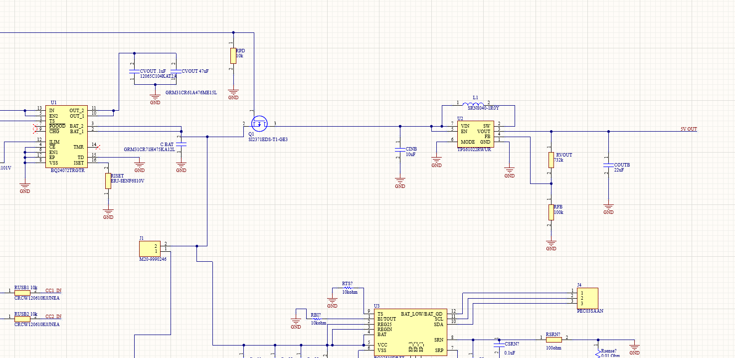
My PCB design will consist of a battery charger, fuel gauge, and Boost converter(TPS61022RWUR) IC primarily. The Battery Charger IC will recharge the battery, the Fuel Gauge will monitor the Battery, and from the schematic, the "J1" represents the battery(3.7V 6000mAh) connector. My goal is is to step up the voltage 3.54-3.7V to 5V to a usb type c to provide power to a Raspberry Pi 4b using the boost converter. I figured 3A output from the boost converter would be sufficient to power the Raspberry Pi 4b.
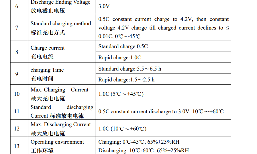
From the datasheet of the battery(3.7V 6000mAh), I see that the Max Discharging Current is 1.0C so I suppose 6A.
But will the 6.5A minimum valley current limit threshold affect my utilization of the boost converter knowing I am using a 3.7V(6000mAh) LIPO battery with a max discharge of 6A from looking at my battery's datasheet? I really want to use this boost converter for my project design. I am also new to electronics and pcb design so any understanding is helpful.
Thank you,
Andres Perez
