This thread has been locked.

If you have a related question, please click the "Ask a related question" button in the top right corner. The newly created question will be automatically linked to this question.

TPS2492: High Powered - Brushed DC Motor Application - Overheated FET Damage / Burnt

Part Number: TPS2492

Hello Everyone in the forum,

We are designing a soft starter controller for our vacuum motor using the TPS2492 chip.

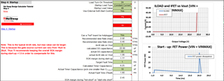
We have attached the design calculator for this motor which is running at a maximum 24V, 25A.

The motor load has an inductance of 0.763mH and 0.8ohm.

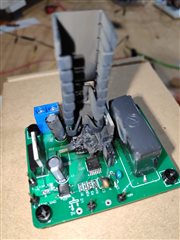
Recently we have tested the circuit and the MOSFET that we are using caught fire.

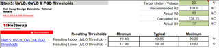
I have filled in the calculator accordingly and seems there is no problem with the calculation

CSD18534KCS 24V 5A.xlsxTPS2492Test.pdf

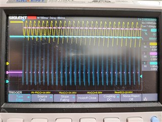
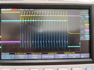
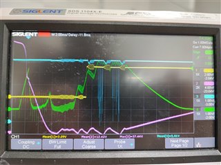
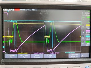
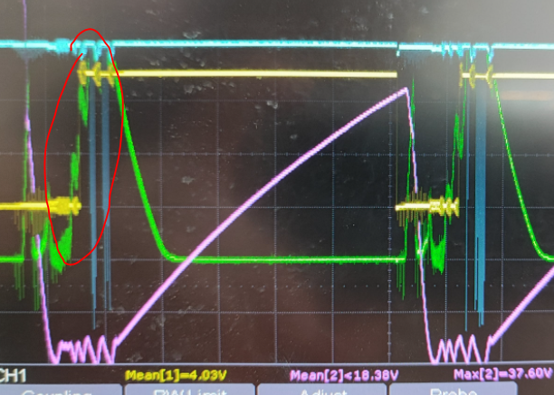
There are a few observations on our test:

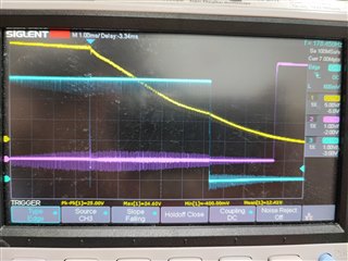
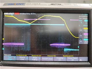
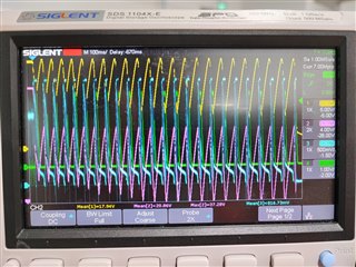
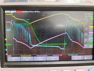
  • When the load current just exceeds the limit, around 5A, the PG and Vout start to react up and down which seems uncontrollable, according to the datasheet, it should cut off after the timer set by CT and never turn on again, apparently not in our case, and the fault is never going to 0V or LOW as a sign of FAULT
  • When the above happened, the MOSFET seems like on the resistance area which actually has a lot of power loss and it is ongoing without the TPS2492 cutting it off.

Is there anything that we miss in this design? I need some help or maybe suggestion that probably TPS2492 is not the right choice

the requirement needed are

  • Overcurrent and short circuit protection
  • Undervoltage Protection
  • Soft Start for Inrush Current
  • Handle Inrush Current caused by a sudden increase of load because of the sudden loading on the motor torque without cutting off the entire circuit
  • Hi Calvin,

    Welcome to E2E!

    I will go through the design and get back by early next week.

    Can you confirm whether you are using RC components during your test ? If yes - how is the behavior without them ?

    Best Regards,

    Rakesh

  • Yes I am using them for now.
    I have not tested without the Rg Cg before but I can try it

  • Thanks Calvin for the information

  • Hi Calvin,

    The design looks fine. The RG2 slows down the discharge of CG2 and then affects the turn-off response of the FET.

    Please reduce the RG2 to 22Ohm and check the behavior. Also, for your design CG2 can be reduced to 10nF.

    Please share the test results of GATE, Timer, FLT, input current for understanding.

    Best Regards,

    Rakesh

  • Okay I will test it with the new value and test again.
    May I know in the future how to calculate the correct RG and CG for other design?
    Because the RG CG is fixed value in the calculator, we thought it is already designed for any kind of application.

    Thank you!

  • Hi Calvin,

    For CG values in the range <5nF, RG of 1kOhm should not be a problem. For large CG values upto 47nF, we should reduce 1k to 22 Ohm to discharge CG fast. Sorry for not being clear in design calculator.

    Beyond 47nF, we suggest to use a local pnp discharge circuit as shown below. This helps to reduce the stress on the GATE as the discharge is local

    Best Regards,

    Rakesh

  • Hello Rakesh,

    I am currently tested this circuit and it actually works
    but I need continuous testing to make sure the fire is not happening again in the future

    By the way, what is the requirement of the Rg here, you mentioned about 22 Ohm, can we choose other value instead? Is there any limit? will it be affected by multiple MOSFET?


    I also found another problem, if you take a look at my circuit diagram in the first question above. I use the PG pin to prevent the signal turning on the motor.
    Apparently, I tried yesterday to give a signal while Enable is low, and then I switched the UVEN on: the motor was directly running and spoiled my MOSFET (the MOSFET is shorted and forever in short condition after that).
    May I know why PG did not prevent this situation? I thought PG will wait to goes low until MOSFET was fully opened to drive the output and current.


    Thank you!

  • Hi Calvin,

    Rg helps to limit the discharge current of Cg  into the GATE pin. Any value between 22 Ohm to 100 Ohm would be good to limit the current.

    Are you sure that the load is disable stated with PG signal. Please note that PG is a active low signal for this device.

    Can you share test wave form of Vout, Iout, GATE, timer for that test case to understand.

    Best Regards,

    Rakesh

  • Hello Rakesh,

    I have done some tests yesterday but I was scoping VOut, PG, and FLT
    There might be something interesting here that the FLT seems to go Low several times and back up again followed by PG.
    When the FLT go down, VOut will follows

    The load is disabled because we cutoff the command by P MOSFET which activated by low signal from PG

    These are pictures when it reached the overcurrent slowly:

    These are pictures when it reached the overcurrent by inrush current:

    Notes:
    Yellow - VOut
    Blue - FLT
    Purple - PG

    My question is why the FLT never latches like what TPS2492 supposed to do?
    Another question is, when FLT goes low, nothing will works right as the PG will go high, Gate will be low and the MOSFET should be open.
    I think the weird part here is, the FLT never latches which causing everything to turn back on again.

    I will try your suggestion for scoping today.

  • Hello Rakesh

    Please take a look on what happen to the overcurrent when it reached slowly

    Notes:
    Yellow - VOut
    Purple - Gate
    Blue - IMon (9 mOhm Rsense)
    Green - Timer

  • Hello Rakesh,

    One more set of pictures to show you different pins together

    Notes:
    Yellow - PG
    Purple - Gate
    Blue - FLT
    Green - Timer

  • Hi Calvin,

    Thanks for the waveforms. I will review and get back by end of this week.

    Best Regards,

    Rakesh

  • Hello Rakesh, thank you!

    If possible if you can take a look earlier, it will be good for me!
    Thanks for your help!

  • Hi Calvin,

    Can you confirm, are these tests with Rg = 22 Ohm. ?

    It looks to me that the load profile is causing the device not to completely shut-off. The system is going to fault and coming out of fault, this is causing lot of stress on the power FET. 

    Can you increase the Cout to 330uF and reduce Cg to 22nF and verify. I thought process is to provide more hold up capacitor for the load to support load transients and reduce Cg to improve the turn-off speed. The design calculator shows no issue with these values.

    Best Regards,

    Rakesh

  • Yes it is, the Rg is 22 Ohm

    How can the system coming out the fault without resetting the UVEN? TPS2492 should be latch to the fault until we reset it out right?

    Does COut means the Snubber that we are currently using must be increased?
    Currently we are using this https://au.element14.com/roxburgh/xe1202/cap-0-2-f-250vac-20/dp/2336099 XE1202 at the Cout instead of single capacitor.

    In any case, May I know what is the requirement of the COut, because our load is inductive load, when the power cutoff, the voltage spike can be very high, that is why we put a Snubber instead of COut.

    Thank you!

  • Hi Calvin,

    The UVLO threshold is at ~23V. Can you please check whether the device is auto-resetting UVEN due to drop in VIN during the fault. If yes, please set UVLO at 18V and test once to confirm. we can proceed next actions, based on the result.

    Yes, I meant Cout in the place of snubber to support transient loads. My thought process is that the Cout will help to support peak currents and avoid triggering timer again and again as observed in the below waveform (Green)

    Best Regards,

    Rakesh

  • Hello Rakesh,

    Thank you for the suggestion, I will check whether the UVLO resetting the FLT or not

    By the way, like I mentioned before, our load is inductive load, and if I put normal capacitor for 330nF 100V instead of snubber capacitor (that can withstand 1200V), I am afraid it will destroy the capacitor.
    The sudden stop in inductive load will give a sudden voltage spike because of Back EMF, the diode actually help but I am not sure about changing capacitor.

    Do you think it is okay to change to an Electrolytic (Polarized) 330nF 100V capacitor instead of a snubber? or should we parallel it together with the snubber?

    Thank you!

  • Hi Calvin,

    The back EMF will find path through the body diode of hot-swap FET to the Vin side. 

    We can use electrolytic 330uF at Cout to check.

    Regards,

    Rakesh

  • Hello Rakesh,

    I took some experiments with 220 uF and it worked better than before
    But I had some problems with the FLT keep restarting. That's when I scope the UVEN and realized that the voltage is around 1.04 to 1.4V when it is trying to shut down before the overcurrent
    The UVEN voltage on normal operation when the Vin 23.8V to 24V is 1.36V to 1.42V with 10K and 137K Ohm resistor.
    We found that probably our SSR creates voltage drop https://www.ixysic.com/home/pdfs.nsf/www/CPC1016N.pdf/$file/CPC1016N.pdf . However if according to the datasheet, it should not affect much

    Our calculation shows 10 and 137 KOhm is for UVLO of 19V which is should be acceptable

    Another question is because we have PG tied to the signal for the load. From Datasheet, PG will only be good when the MOSFET is ready.
    So in the event that somehow the signal to the load will create an inrush current that exceeds the current limit at startup, it will not burn the MOSFET, won't it? Because the PG will wait until the FET is ready and then the inrush current will go in.

    However, we had a few occasions previously that our FET spoiled when the signal is on before the UVEN was on which then after we turn on the UVEN, the load will directly run and afterward, our FET is already shorted. Do you know what could possibly happen? So far we have spoiled 6+ FET because of the accidental turning on the signal before the UVEN, even though we have already put PG pin as the signal to let the Load signal go through.

  • Hi Calvin,

    I didn't get chance to go through this today. I Will get back by Friday.

    Best Regards,

    Rakesh

  • Hi Calvin,

    Agree with you on the UVLO calculations.

    Regarding FET failures - the FET would undergo severe SOA stress during startup if the load is enabled. 

    Please include the startup load information in the design calculator and verify the SOA margin.

    Best regards,

    Rakesh

  • Hello Rakesh,

    Sorry for the UVLO, actually my calculation is correct on the calculator, but in reality, it actually drops so much that it actually caused the restart of the UVLO so I need to put the UVLO much lower to act normally.

    Is there anything that I can test to verify this UVLO voltage drop?

    You can see my calculator in the first post of this thread.
    The SOA Margin is very high even I put crazy number like 40A, it's still okay

  • Hi Calvin,

    Can you check whether the voltage drop is due to the input source impedance? If it is not a hot-plug system, you can consider increasing Cin of the hot-swap

    SOA margin looks good.

    Best regards,

    Rakesh