This thread has been locked.

If you have a related question, please click the "Ask a related question" button in the top right corner. The newly created question will be automatically linked to this question.

TPS65313-Q1: question about the block diagram in slvaeo0.pdf

Part Number: TPS65313-Q1
Other Parts Discussed in Thread: AWR1843, TPS65131, TPS65653-Q1, , LP87745-Q1

Hi,

My customer would like to design a AWR1843 system with functional safety supported. They checked the app note slvaeo0.pdf and found there is a System Level Detailed Block Diagram.

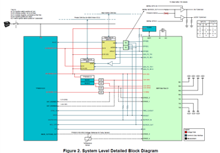
They thought the block diagram is designed to support functional safety. They would like to know what this system will do when TPS65313 or TPS65653 is undervoltage or overvoltage.

When undervoltage or overvoltage happens:

From the datasheet of TPS65313, we know the PMIC will disable the issue output channel and can send out signal to reset of the primary system MCU or DSP. 

From the datasheet of TPS65653, external processor can be interrupt by the nINT pin.

AW1843 may not work normally in this condition as some of the power rail is abnormal.

Customer thought in this condition, the system power its self should be reset or restart, but they don's see such design in the block diagram. Would you pls kindly help?

My suggestion is to use the watchdog signal of TPS65131 to trigger external circuit to reset the whole system. But customer would like you to suggest what the system you design will do in this condition?

Thanks,

Chris

  • Hello Chris,

    The engineer assigned to this ticket will be back in the office early next week so you should have a response by Tuesday.

    Regards,

    Alex

  • Hi Chris,

    TPS65313-Q1 external/general purpose voltage monitors are monitoring TPS65653-Q1 1.8V rail for UV/OV and if UV/OV detected, TPS65313-Q1 will reset the AWR1843. TPS65653-Q1 1V rail is monitored by AWR1843 ADC itself and if UV/OV is detected on this rail, AWR1843 will put the system in safe state. AWR1843 internal ADC is supplied by 1.8V rail and hence it is independent from 1V rail and hence such monitoring is ok. Also TPS65653-Q1 reset pin or nINT pin are not used in this safety concept and this is acceptable.

    If customer is starting new development, I recommend them to use our new PMIC, LP87745-Q1 as it reduces overall solution cost and it has much better noise and load transient performance. Please visit this device product page and also you can take a look at AWR2944B EVM.

    www.ti.com/.../LP87745-Q1

    Regards,

    Murthy

  • TPS65653-Q1 1V rail is monitored by AWR1843 ADC itself and if UV/OV is detected on this rail, AWR1843 will put the system in safe state

    Murthy,

    Thanks for your reply!

    Would you pls help to provide more detail on "AWR1843 will put the system in safe state"? What does AWR1843 will do? Stop radar processing and send error info to the car by CAN interface?

    Best Regards,

    Chris

  • Hello Chris,

    Your understanding is correct on CAN error message. 1V rail is mostly used for RF transmit/ receive function and even if 1V power is not present, AWR18xx is still operational (of course without RF transmit/receive function) and it can provide the error information over the CAN interface and inform the central ECU. From safety point of view, 1.8V, 1.2V and 3.3V rails are more critical.

    Regards,

    Murthy

  • TPS65313-Q1 external/general purpose voltage monitors are monitoring TPS65653-Q1 1.8V rail for UV/OV and if UV/OV detected, TPS65313-Q1 will reset the AWR1843.

    Murthy,

    I checked the EXT_VMON1_CFG and EXT_VMON2_CFG registers info in TPS65313 datasheet, I found the device response to fault detection from the monitors is to transit to safety state or reset state. Will the device reset AWR1843 in reset state?

    If after resetting AWR1843, the output of 1.8V is still abnormal due to PMIC/Power chip issue or external power input issue, what do you consider for the safety function of the system?

    Thanks,

    Chris

  • Hello Chris,

    When you configure EXT_VMON1 to generate a reset if UV/OV detected, then NRES will be asserted to reset the AWR and PMIC error counter gets incremented. If 1.8V rail is still has issues, then PMIC again detects this error and error counter is incremented again and NRES is asserted. This will repeat until PMIC error counter reaches its threshold (configurable through software) and PMIC goes to off state, all the PMIC outputs are turned and ECU is in safe state/ off state.

    Regards,

    Murthy