This thread has been locked.

If you have a related question, please click the "Ask a related question" button in the top right corner. The newly created question will be automatically linked to this question.

TPS6594-Q1: NVM about TPS65941213RWERQ1

Part Number: TPS6594-Q1
Other Parts Discussed in Thread: TPS6594EVM, , TDA4VM

Hi  TI Expert:

because of the COVID-19 , it will  took a long time to get the TPS65941213RWERQ1  samples.

For I have compared the register configuration of NVM of tps69541212, tps69541213 and tps69541111. There is a detailed configuration in this post.

I found that the NVM configuration lists of tps69541213 and tps69541111 are identical, only some NVM register value are different. 

So  can I use attached NVM files  to reProgram the  TPS69541111  or TPS6954-Q1   to obtain  TPS65941213RWERQ1 ?

If this method is feasible, what should we do next?

  • I don't see any attached files in your post. I can not confirm if the files you are referring would work.

    It is possible re-program a TPS65941111 to behave like a TPS65941213, but there are some caveats as some registers can not be overwritten. It is recommended that this only be done for prototyping efforts and not mass production.

    Do you have a TPS6594EVM?

  • attached file is in the below post :

    https://e2e.ti.com/support/power-management-group/power-management/f/power-management-forum/1051288/tps6594-q1-default-values-of-tps65941212rwerq1-and-tps65941111rwerq1-by-nvm-setting/3889848?tisearch=e2e-sitesearch&keymatch=TI_DEVICE_ID%3D0x82%20TI_NVM_ID%3D0x13%20TI_NVM_REV%3D0x2#3889848

     you mentioned that TPS65941111 or TPS65941213 have some registers cannot be overwritten, so does  this mean  they can only program once from the TPS6594-Q1?

    Can   TPS65941111  or TPS65941213  be programe to alternately?  such as a TPS65941111  be program to TPS65941213  or a TPS65941213 be program  to  TPS65941111?

    what is the prototyping efforts  you mentioned above?   

    thanks!

  • The files in that post can not be used to reprogram a device. They are only useful for comparison purposes. Furthermore, they are pre-RTM versions of the device.

     you mentioned that TPS65941111 or TPS65941213 have some registers cannot be overwritten, so does  this mean  they can only program once from the TPS6594-Q1?

    Can   TPS65941111  or TPS65941213  be programe to alternately?  such as a TPS65941111  be program to TPS65941213  or a TPS65941213 be program  to  TPS65941111?

    Register 0x01 to 0x03 contain device identification information. They are locked after a device leaves our factory. A TP65941111 can still be reprogrammed to behave as a TPS65941213, but these 3 registers will say it is an '1111. The same thing would happen if a TPS65941213 was reprogrammed as a '1111.

    what is the prototyping efforts  you mentioned above? 

    Prototyping efforts such as reprogramming a few units to test out a PCB design or to get started on software development. Devices reprogrammed between established NVMs should NOT be used in final hardware releases.

    Do you have a TPS6594EVM? If so, I can provide instructions for programming the device.

  • Hi TI Expert:

    We have brought a tps6594evm and some tps65941111 chips.

    So Can you help  to provid the methods or instructions  for programming tps65941111 to behave as a TPS65941213?

    In addition, to program the chip on the evaluation board, We need to weld the tps65941111  chip to the board, and then remove the programmed chip from the board.  It needs repeated welding the chips , which is troublesome.

    Is there a suitable tooling that can program the chip without repeatedly welding the chip to the evaluation board?

    thanks!

  • You can solder the TPS65941111 devices you intend to change onto the boards that will use them as '1213s by themselves. Then follow the instructions below before populating an '1111 in the PMIC-B location.

    Hardware Setup

    1. Solder target TPS65941111 unit onto board location where it will be used as a ‘1213.
    2. Connect I2C lines from EVM to board with ‘1111.
    3. Remove any jumper between VSYS and V5V0 or V3V3.
    4. Connect USB-C cable to J22 on EVM
    5. Apply power to target board with ‘1111, make sure EN pin is pulled low.

    Software Instructions:

    1. Follow section 5 of this user guide for installing and launching GUI.7510.slvubt8a.pdf
    2. After establishing I2C communication between the GUI and target device, follow section 8.2 to program the target device with the attached binary file.

    DZ TPS65941213 PDN-0C-1A (LeoA 3-phase) RTM-Rev 4.0.bin

  • Hi  TI Expert:

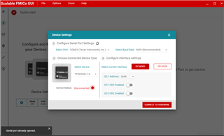
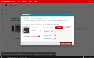
        I got a TPS65941111EVM in hand recently. But when we use a USB cable connect  the EVM board through I2C MODE ,the GUI can not connect the hardware. the GUI show a figure as below:

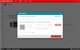
    Only in the SPI  MODE  ,the GUI can  connect the hardware. as below figure:


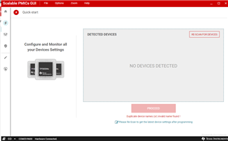
    after we enter the  Quick-start page ,we can not find the device. the GUI displays:  NO DEVICES DETECTED ,as below figure.

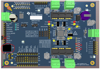
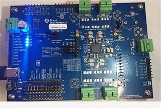
    it seems we have a right jumper configure for J7 ,SPI_EN ,and J37 MASTER/SLAVE select.for the TPS65941111 is a slave ,we jump the J37 as a single PMIC EVM and force the PMIC as MASTER.

    we also  found that the EVM board version is BMC047A . what is different  with the BMC047E3,which is in  User’s Guide of TPS6594x-Q1 Evaluation Module.

     we found BMC047A  has a little difference with BMC047E3 .such as J47 ,only BMC047A has a J47 jumper. 

    so can you help to answer:

    1 Does  BMC047A board have the same jumper with BMC047E3 ? 

    2 we can only connect the hardware through SPI MODE. but as  you mentioned  above, it  is connect  I2C MODE.  how to configure the board to I2C MODE .

    3 how to power up the TPS65941111 through the GUI ?

    thanks !

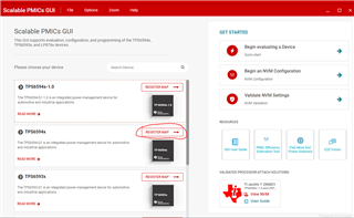
  • Do not use the quick start page. Use the register map page or NVM configuration page. Make sure to select TPS6594x for device.

    The TPS65941111 is at I2C address 0x4C.

    Can you confirm communication now? Do not expect the rails to power up. The '1111 is not configured to operate as a standalone device which means it will enter into standby mode if not connected to a '1213 or '1212.

  • Hi Ti Expert:

    I change  the I2C address to 0x4C  ,and the GUI can not connect the hardware. Only the SPI MODE does the GUI connect the hardware.

    Only we derectly connect a 3V3 power supply to VCCA ,the I2C MODE can connect the hardware. it seems that the VSYS has not feed to the chip VCCA.

    Does this caused by the different hardware versions? 

  • Hi Ti Expert:

    I  change  the I2C address to 0x4C  ,and the GUI I2C MODEcan not connect the hardware. Only the SPI MODE does the GUI connect the hardware.

    after I  directly connect a 3V3 power supply to VCCA(J28  in the EVM) ,the I2C MODE can connect the hardware. it seems that the VSYS has not  feed to the chip VCCA,it need a external 3v3 power to VCCA 。

    After establishing I2C communication between the GUI and target device, I program the  DZ TP S65941213 PDN-0C-1A (LeoA 3-phase) RTM-Rev 4.0.bin  files into  the device and GUI prompting a message that  NVM program is success.

    I  repower up the device in the EVM ,and find that the default  configuration of TPS65941213 have no output .

    Only  modify the register of   BUCK1_CTRL Register:BUCK1_EN ,from  "BUCK regulator is disabled" to "BUCK regulator is enabled" , the BUCK1 output  0V8 power , and the BUCK4 output 0v85 power.

    Our design is use TPS65941213   as primitive PMIC for TDA4VM, So I infer that TPS65941213  must have a default output for the MCU domain .  but do not see any output in the EVM after  powerup the board.

    we reference the TPS65941213  from TDA4VM Edge AI Kit - DUAL TPS65941x PMICs . it is as belw link:

    www.ti.com.cn/.../sprr438

    this reference design use TPS65941213 as primitive  PMIC for TDA4VM ,and BUCK4 is for TDA4VM  MCU domain power.

    Question 1 : TPS65941213 is the primitive PMIC of TDA4VM. BUCK4 output VDD_MCU_0V85 for the TDA4VM MCU core power supply. ,if TPS65941213  has not a default output of BUCK4 , How can TDA4 MCU domain boot up ? 

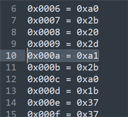
     I  open the BIN files you given above ,and found that all the BUCK output are default disabled. So I modify the address 0x0a value from 0xa0 to 0xa1 ,this value  enables the BUCK4 output .and  save it as a new BIN file. then I reprogram the new BIN file to the EVM device.

    Question 2:  After program the new BIN file(which modify a register value )  into the device ,and reboot it , that the GUI can not Connect the hardware through the I2C MODE .

    Does this cause by the modified BIN file program the device? How can we fix the problem? 


    thanks!

  • Important things of note:

    1. Neither the TPS65941213 or TPS65941111 are meant to work as stand alone devices. They are meant to work as a '1213+'1111 pair and the PMICs will not power up fully otherwise.
    2. The "default" register values of the bin file only represent what gets loaded into the register when it enters the INIT state when VCCA crosses the UVLO threshold. These values change according to a devices programmed finite state machine as it enters different functional modes. For example, all the rails are disabled in the INIT state but become enabled when the PMIC enters the ACTIVE state
    3. Because of #2, it is important to NOT modify the .bin file
    4. Neither '1213 or '1111 are programmed to communicate via SPI. The SPI_EN jumper just enables a translator on the EVM but doesn't change the settings of the PMIC

    Questions:

    1. The '1213 and '1111 have different phase configurations for BUCKS1-4. If the connections are incorrect, the PMIC will not fully power up. Referring to the below table, '1213 is configuration 2 and '1111 is configuration 1. These jumpers and resistors are on the bottom of the EVM.

    2. Prior attempting to program the bin file, how did you confirm you established communication with the PMIC? Did you go to the register map page and attempt to read any of the registers?

  • We remove the J25 Jumper ,and solder the R7 Res .Repower the EVM ,and the I2C MODE can connect the hardware .it seems that the error jumper cause the EVM fault to connect the i2c device.

    Also ,we remove this device from EVM and solder it in our board which is TPS65941213 ( device from EVM) + TPS65941111 ,power up the board ,we can get the right power supplys,as it is described in the PDN-0C document .

    thanks!

  • Hi Ti Experts:

      Last time, we program the TPS65941111 EVM device  as a "TPS65941213", remove the device from the EVM board, then solder  it in our board ,  which beheave as TPS65941213 ( device from EVM) ,and slave device is  TPS65941111 . both "TPS65941213"  and TPS65941111  work correctly, the out put voltage are all correctly.

    So we program  TPS65941111 chips  on our hand as "TPS65941213", and solder them in our other boards  .Unlike before ,the TPS65941111  programe as "TPS65941213" can not work correctly  . Master device only output VOUT_LDOVINT and VOUT_LDOVRTC .   BUCKS1-5  do not output any voltage.  We have program two pieces of TPS65941111 ,and solder in same two pieces boards , both behave the same.

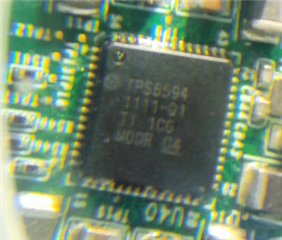
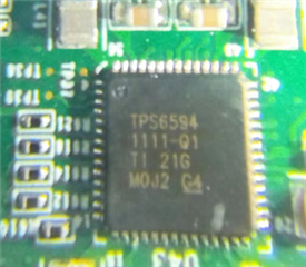
    We found that the  device from EVM and on our hand have different silkscreen.

    Device remove from EVM  is  :TPS65941111-Q1 TI 1CG M0OR G4 ,as below figure,which works well.

    Device on our hand is : TSP65941111-Q1 TI 21G M0J2  G4 . as below figure,which can not work.


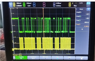
    we check the SPIM communication between " '1213"and '1111 chips. and found in the correct boad(which 1213 is program from EVM device),  the  SPMI communication is continusly have signals. 

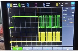
    we also check the uncorrect board(which 1213 is programed from our hand)   SPIM communication between "1213" and "1111" ,found that only Started 40us ,master and slave have communication  signals ,and after, there are no signals in the SPIM bus.


    Questions

    1 : Does the “1213” in our board can not work is caused by the silkscreen,what different between these?

    2: How to bring up the "1213" in our board ?If the 1213 chip been programed is correct ,how to Locate the PMIC problems?

    thanks!