This thread has been locked.

If you have a related question, please click the "Ask a related question" button in the top right corner. The newly created question will be automatically linked to this question.

TPS61169: PSPICE MODEL FOR TPS61169: PMW DUTY CYCLE TUNNING DOESN´t WORK

Part Number: TPS61169

Greetings TI members.

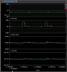
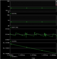
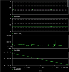
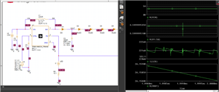
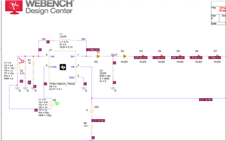
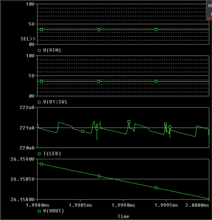
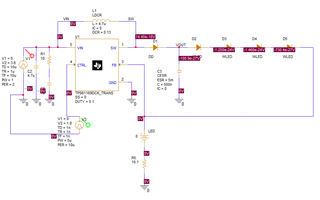
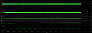
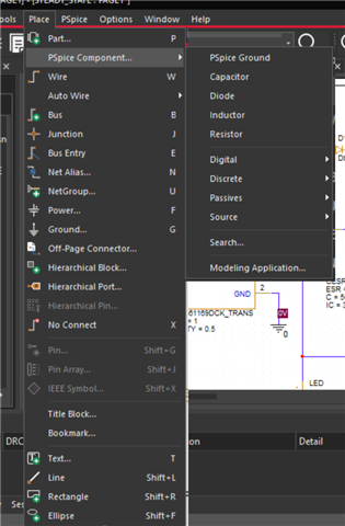
I am simulating using PSpice for TI, since there I can find a Pspice model for the LD driver TPS61169However, it is not possible to simulate a situation different PMW signal we supply to the CTRL port has a duty cycle different to 100% . I am using the test bench circuit from TI and by changing the DUTY parameter on the TPS61169, it just gives a completed ruined output. 

It is possible to observe the signal according to the desired duty cycle of the PMW dimming control signal?  

  • In addition, if I use a lower number of LED diodes, the output voltage remains in around 30V. It is expected that the voltage value would be around 12V and not that high. Therefore, the circuit is just not working at all.

  • hi Francisco

       Do you mean that the LED current does not change by PWM duty cycle? Is there any error information?

      If not, can you provide simulation results of SW voltage, FB voltage, inductor current, LED current. thanks

  • Good day. Sorry for the late answer, I was on a short holyday.

    Today I will provide a capture of the plot from the requested variables. Just give me some minutes

  • thanks, wait for your feedback.

  • Hi Mason,

    I took a while to provide a full simulations to illustrate the problem. I was using the testbench I downloaded from Spice for TI: 


    And I obtained the following:

    1) Just setting DUTY = 1 without changing the circuitry:

    2) I now set the D=0.9. From this value and bellow, there is no coherent result, and the signals look broken:

    3) I changed to 0.5 without significant difference in aspect:

    4) Just to demostrate that the model might not be correct, I simulated without any signal to the CTRL port and DUTY=1 (It should not provide any signal at all but it was working as if it has a DC signal, or 100% Duty cycle PMW):

    5) Finally, I connected an actual PMW source with 90% duty cycle and DUTY=0.9 on the LED driver. No change is observed:


    As it seems, the Spice model seems to not be working properly. 

  • hi Franciso

       please try following actions:

    1. delete C5 (1uF)

    2. decrease PWM frequency to 50kHz

  • Hi  Mason

    after changing the listed elements, the results still the same

  • In addition, I observed that the Pspice model doesn´t modify the DUTY parameter although it is changed from the circuit. 

  • hi Francisco

       Do you mean that the duty cycle of source V4 has not been changed although the on time period is 9u? 

       Can you please clarify your modification on the circuit?

       I faced a problem to download the pspice simulation file. I will try again and check the simulation file. right now you are using following model?

    TPS61169 Unencrypted PSpice Transient Model Package (Rev. B)

  • hi Mason

    My changes were: 

    removing C5

    Decreasing PMW frequency to 50KHz

    The model you provide is exactly the same I got from Pspice with TI.

    I have changed the duty cycle of V4 and in the integrated, and the circuit is still broken regardless.

    In Addition, I just discovered that when I connect the FB port, the IC stop working and provide weird values to the FB pin (values like 14V appears in that pin). 

    I also tried to use the already default circuitry and just change the number of diodes at the output, and the values are again incoherent. 

    It looks like the model is very defective because once I disconnect and delete the IC and run the simulation, the software runs normally and even updates the bias points correctly. When I put back TPS61169, all the bias point values never updates and the plot values are not correlated to the DC values (I am having 14.1V at the feedback loop pin while the plot is marking an oscillating signal between 18 and 18.5mV). 

  • hi Francisco

       I have tried the simulation model and it can work after some modifications. I added a PWM pulse source at CTRL pin, the frequency is 10kHz, 50% duty cycle. Please ignore the DUTY set in the device, I do not think it works after trying different DUTY values. The LED current is scaled down according to duty cycle.

  • Hi Mason

    I repeated your circuit exactly as you did and I got the same results as you. However I tried to build the circuit from the Steady State circuit, and basically every movement I do on that circuit, it brakes the IC function.

    I could have my circuit running by replacing carefully piece by piece and finally I could simulate the desired situation. However, the IC is not working stand alone since I tried to also build the circuit from blank and is not working well (again the same odd value).

    Can you attempt to build the circuit from blank (the same from the TI test bench) and see if the IC works as intended? it is to discard a possible issue that is happening on my side.

  • hi Francisco

       What is your required operation condition? Can you clarify you issue?

      Besides, is it available to describe a little bit on your application here?

  • Hi Mason.

    Unfortunately because of secrecy, I cannot give you so much details about my design more than the following:

    - Rather than using 10 Diodes string, is just 4.
    - PWM ampllitude is 1.8V at 100kHz.

    What I wanted to do is to adapt the IC to work with my own setting.

    My problem is that when I build the circuit by myself (on a new project), and I run the simulation from a value different than Duty=1. Basically the IC doesn´t work because I get the same results as I showed before: 

    It seems the IC crashes and stop working because there is not current switching and the inductor is not doing anything. This is an indication that the current switching is not happening at all. This happens also when I remove some of the diodes from the test bench circuit. 

    What I would like is to have a functional IC that works independently from the pre-made test bench. As I said, I just created a new project and rebuild the same circuit as the test bench and the IC just doesn´t work anymore. That is why I think, if you also build the same circuit from a blank project and still, it is possible to provide dimming control without the IC crashing, then I can adapt that design to my requirements without any risk.

    Can you follow my idea? 


  • hi Francisco

       Please see the result. I can simulate you condition correctly with following condition:

    Vin=3,6V, LED 4 in series, PWM 1.8V, 100kHz, 50%duty cycle.

  • Hi Mason


    I replicated the circuit but I am still having the odd result when I do it on a separate project. But I have a final question: How do I get access to the WLED and the LSCR and CESR components? I tried to find them on the library but I was not able and I had to copy them from the Test setting.

  • Our experts for this issue are currently celebrating the Chinese national holiday, and they will respond next week.

  • hi Francisco

        You can add any components you want as below, diode, inductor or capacitor. The values can be set based on your requirement.


  • Hi Mason. 

    However when I use those devices are actually ideal devices. I  cannot find where to edit ESR or anything else. When I checked the Pspice models for those components, they are part of the TPS61169. The components you said are default components. 

    How can I get access to those components that are listed on the TPS61169 library? 

  • hi Francisco

       I did not find the way to get this either. 

      Have you gotten any normal waveform by either having modification on existing model or building a new project?

      The aim is to get the simulation result under below requirement by any available way?  If so, I can send you the modified project. 

    Rather than using 10 Diodes string, is just 4.
    - PWM ampllitude is 1.8V at 100kHz