This thread has been locked.

If you have a related question, please click the "Ask a related question" button in the top right corner. The newly created question will be automatically linked to this question.

BQ27411-G1: Full Available Capacity seems to be incorrect

Part Number: BQ27411-G1
Other Parts Discussed in Thread: EV2400

Hi,

I'm using BQ27411DRZT-G1A on my custom PCB.

My settings:

DESIGN_CAPACITY = 2200
NOMINAL_VOLTAGE = 3.7
DESIGN_ENERGY = DESIGN_CAPACITY * NOMINAL_VOLTAGE
TERMINATE_VOLTAGE = 3000
TAPER_CURRENT = 70
TAPER_RATE = (DESIGN_CAPACITY / (0.1 * TAPER_CURRENT))
QMAX_CELL_0 = DESIGN_CAPACITY

Rest of the Data Memory Configuration is set to typical values (from SLUUAS7B–January 2014–Revised June 2015 datasheet).

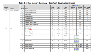
Then after exiting cfgupmode and waiting several seconds I read FullAvailableCapacity() (COMMAND CODE = 0x0A) and DesignCapacity() (COMMAND CODE = 0x3C).
Value of Design Capacity is correct - equal to what I set. I expect that Full Available Capacity will have similar value as Design Capacity, but the value is significantly different.

So I decided to test diffrent Design Capacity values. Here is what I get:

design capacity full availiable capacity
1000 61
1500 136
2000 242
2100 267
2200 292
2300 321
2400 350
2500 378
2600 409
2800 476
3000 545
5000 1514
6000 2181
9000 4906

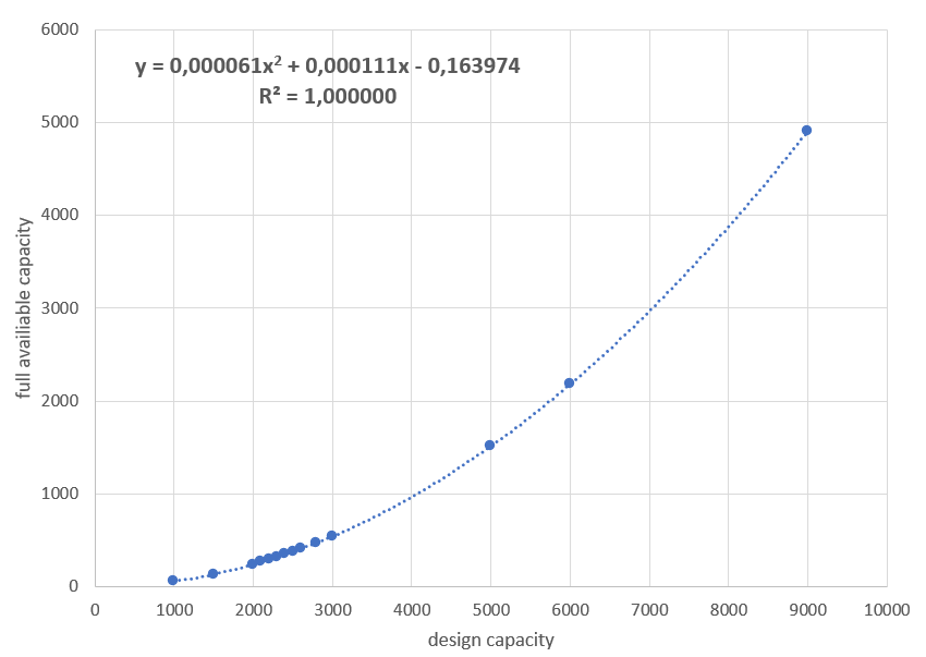
Is this correct behaviour or something is wrong?

  • Hello Krystian,

    I think the error here is due to units. Reference this section of the TRM:

    I checked your numbers you provided against the formula and they seem to match exactly what I would predict. You would have set up a scaling factor for writing QMAX to accomplish this. Or, just don't write anything to this value (QMAX). Simply sweeping design capacity should work because the gauge will multiply that value by 1 to determine the QMAX. In general, you shouldn't write to QMAX because the gauge will update it by itself. Let me know if making this change works for you, or if you would like more explanation.

    thanks,

    Alex M.

  • Hi Alexander,

    thank you for replay.

    I tested yours suggestion. Now value of Full Available Capacity is even smaller and not always the same for specific Design Capacity. When Design Capacity was set to 2200 I read Full Available Capacity e.g. 83, 68 right after configuration.

    StateOfCharge() changes much faster than expected for the capacity of the battery used. The same SOC behaviour was observed when I was setting QMAX.

  • Hello Krystian,

    Can you share the specific values you are setting and the results? Is it possible that QMAX_CELL_0 is still set to some other value? For the SOC issue, what is the actual capacity of the battery? I would expect the SOC values to be inaccurate if the gauge has the wrong idea of Qmax or a mismatch with the actual battery capacity. 

    thanks,

    Alex M.

  • Hi,

    my LI-ION 18650 battery have 2200 mAh.

    I attach PDF with configuration:

    BQ27411-G1A_config_2022-04-13.pdf

    And here is charge - discharge - charge cycle:


  • Hello Krystian,

    Thanks for providing these. I see what you mean by the SOC now. It appears the gauge has calculated an extremely small FCC like you mentioned earlier and thus the SOC changes rapidly. When I look in your configuration. I see a dash on QMAX CELL 0, I believe that means default? It should be 16384 then, but maybe it is still stuck at some lower value from earlier? Can you try writing 16384 to QMAX CELL 0 in a similar manner to how you did it initially to see if that helps?

    If we see the FCC change to be close to 2200mAH that will be good. But even if we see FCC go to some other value, then we know at least that the QMAX CELL 0 is playing a role in this somehow. And if it doesn't change at all, we can investigate why that is happening. Hopefully this will reveal the issue. Another thing to consider, is doing a full reset of the gauge, but it may not be necessary yet.

    thanks,

    Alex M.

  • Hello Alexander,

    thank you for the quick reply.

    I see a dash on QMAX CELL 0, I believe that means default?

    I forgot to mention that the dash means I don't change these parameters, so they have default values.

    Another thing to consider, is doing a full reset of the gauge, but it may not be necessary yet.

    Before configuring the fuel gauge (with values from BQ27411-G1A_config_2022-04-13.pdf file from my previous message) I disconnected the battery so full reset should occurred.

    Can you try writing 16384 to QMAX CELL 0 in a similar manner to how you did it initially to see if that helps?

    Ok, I will try to write this value.

    Best regards,

    KK

  • Hello Alexander,

    Can you try writing 16384 to QMAX CELL 0 in a similar manner to how you did it initially to see if that helps?

    I tested that, here is result:

    DESIGN_CAPACITY = 2200, QMAX_CELL_0 = default, result FAC = 68
    DESIGN_CAPACITY = 2200, QMAX_CELL_0 = 16384, result FAC = 69

    Default value means value that gauge have after full reset. FAC - Full Available Capacity.

    It seems that changing QMAX_CELL_0 effects FAC value.

    Additionally I tested some other configurations:

    DESIGN_CAPACITY = 2200, QMAX_CELL_0 = 30000, result FAC = 74
    DESIGN_CAPACITY = 6000, QMAX_CELL_0 = default, result FAC = 186
    DESIGN_CAPACITY = 6000, QMAX_CELL_0 = 6000, result FAC = 227
    DESIGN_CAPACITY = 1340, QMAX_CELL_0 = 16384, result FAC = 42

    Parameters dependent on DESIGN_CAPACITY:

    DESIGN_ENERGY = DESIGN_CAPACITY * NOMINAL_VOLTAGE
    TAPER_RATE = DESIGN_CAPACITY / (0.1 * TAPER_CURRENT)

    Best regards,

    KK

  • Hello Krystian,

    We are checking on the data received, we will respond by tomorrow.

    In the mean time, do you have an EV2400 that you can test with so we can confirm all the data register settings read by your host are the same as our toolchain?

    Sincerely,

    Wyatt Keller

  • Hi Wyatt,
    thank you for information.
    Unfortunately I don't have EV2400. However voltage and current that I'm reading have proper values.

    Best regards,

    KK


  • Hello Krystian,

    Here are two other things we can check. Firstly, can you read the temperature? The FAC is generated by simulating with a very small load, because of this, it is similar to the theoretical Qmax. If your temperature configuration is wrong/not connected, the gauge may predicting based on an extreme temperature. Since the simulated load is small, the effect of resistance predicted is small though.

    More likely, there is something going wrong with the communication. Double-check the endianness in particular. Also, in your original post, you put in 6000 as design capacity and QMAX, and got back 2181 for FAC. Why do you now get 227 for the same input? These inconsistencies suggest to me some communication issue with the gauge. This is where an EV2400 can really help, but you can also try checking on a scope or logic analyzer to make sure all the signals are as you expect from the host.

    thanks,

    Alex M.

  • Hello Alexander,

    Firstly, can you read the temperature?

    Unfortunately I won't be able to do it until the middle of next week.

    Also, in your original post, you put in 6000 as design capacity and QMAX, and got back 2181 for FAC. Why do you now get 227 for the same input?

    I full reset the gauge, configure it and get 227 for three attempts. The main difference I notice is that for original post I have just reconfigure gauge with new values without full reset for the whole test. I don't remember exactly but the battery voltage varied by about 200 mV between these two cases.

    I will prepare an example of writing and reading one of the parameters with my host.

    Best regards,

    KK

  • Hello Krystian,

    Please do get those readings. The values in your original post line up 100% with the gauge's equation for calculating Qmax/FAC, but these new values don't seem to line up at all. In addition, the voltage of the cell has no influence on the calculation, so I don't think that could explain the difference. The only things I can think of at this point are communication issues or something with the setup that has changed. 

    thanks,

    Alex M.

  • Hello Alexander,

    I found that changing Sleep Current in State Subclass influences FAC value.

    So I tried one again writing 16384 to QMAX_CELL_0 without changing Sleep Current (leave the default value):

    DESIGN_CAPACITY = 2200, QMAX_CELL_0 = 16384, result FAC = 2183

    Firstly, can you read the temperature?

    Here's what I get:

    Temperature() =  23.05°C
    InternalTemperature() = 23.04°C

    It seems to be correct.

    Tomorrow I will prepare an example of writing and reading one of the parameters with my host.

    Is there a recommended maximum current during battery relaxation to successfully perform Learning Cycle or do I just need to control dV/dt? Though dV/dt is the result of the current.

    Best regards,

    KK

  • Hello Krystian,

    On one hand, it looks like leaving the sleep current on default seems to fix the issue. On the other hand, I don't know why it would do that. Sleep current should have nothing to do with this calculation.  Therefore, it is a bit worrying for the system that we still don't really know why this happened. I would suggest changing it back and forth to confirm it is sleep current at fault, and double-checking that the offset is correct and isn't accidentally writing to the wrong register or something. 

    As for the temperature, I thought that may be the issue but it looks fine, thanks for providing that. I don't think you will need to provide any captures of reading and writing; it seems everything is working okay. It is more likely for there to be typos in the code than for there issues with the signals themselves. Of course, the captures can help you find typos, so it can still be helpful.

    As for the last question, there should not be any current/load during relaxing. However, a small amount of draw from MCUs and other components should not be a problem. It depends on battery capacity and chemistry so its hard to give an exact number. But if you are worried about quiescent/sleep current draw causing issues, it should be fine. If there is some constant, significant load on the battery, it may be necessary to disconnect it for the learning cycle. 

    Feel free to reply with more questions/information.

    thanks,

    Alex M

  • Hello Alexander,

    I think I found a problem with setting sleep current. This is a 2 bytes parameter, with an offset of 31. So to write it, I shall:

    1. Write Subclass ID to DataClass().
    2. Write 0x00 to DataBlock() - offset is 31
    3. Read BlockDataCheckSum()
    4. Read 1 byte at offset 31 - first byte of sleep current old value.
    5. Write 1 byte at offset 31 - first byte of sleep current new value.
    6. Calculate and write new BlockDataCheckSum().
    7. Write 0x01 to DataBlock() - offset is 32
    8. Read BlockDataCheckSum()
    9. Read 1 byte at offset 32%32 - second byte of sleep current old value.
    10. Write 1 byte at offset 32%32 - second byte of sleep current new value.
    11. Calculate and write new BlockDataCheckSum().

    Thank you for your help.

    Now I will test the discharge-charge cycle and try to perform a learning cycle.

    Best regards,
    KK

  • Hello Krystian,

    I think I see, was the problem that sleep current's second bytes' offset stretches into the 0x01 section? I any case, glad to see everything is working as expected for now. Best of luck on the learning cycle, and if you encounter any issues, feel free to start a new thread.

    thanks,

    Alex M.