This thread has been locked.

If you have a related question, please click the "Ask a related question" button in the top right corner. The newly created question will be automatically linked to this question.

LM5170-Q1: SYNC issue

Part Number: LM5170-Q1
Other Parts Discussed in Thread: LM5170

Hi Team,

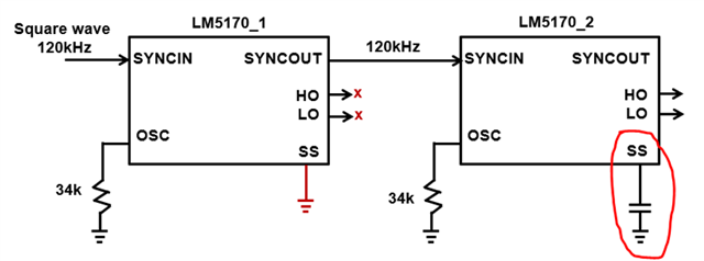
My cusomter is using LM5170-Q1's SYNCOUT signal to provie external clock signal for the downstream LM5170-Q1, like the figure below(control 2-phase boost totally).


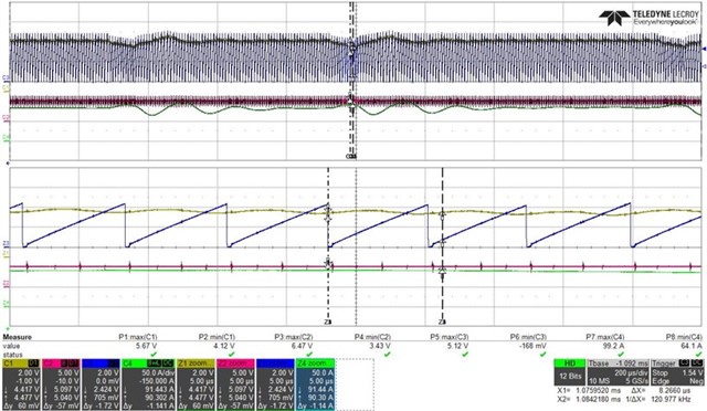
While the output load is increasing to heavy load, COMP and RAMP signals will become unstable.

CH1: COMP; CH2: VIN; CH3: RAMP

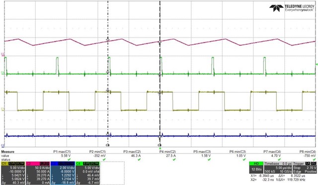
The SYNCIN and SYNC out signals of upstream LM5170-Q1 are both 120kHz.

CH1: SYNCIN; CH4: SYNCOUT

And if customer chooses to set the frequency of downstream LM5170-Q1 by its own OSC resistor, PSU can work nicely under heavy load condition.

Pls help to provide your insights of this issue, thanks.

  • Hi Charles,

    Thank you for reaching out. I need more information about the configuration.

    Is the power stage only controlled by LM5170_2? What is the purpose for LM5170_1? Please share the full schematic if possible.

    Could you also let me know what the other channels are in the two waveform?

    Thanks,

    Yinsong

  • Hi Yinsong,

    Customer is planning to change their design from orignal 4-phase to 2-phase, so they just disable LM5170_1 by connecting SS pin to GND to verify the function on the bench. Customer is not willing to share the schematic since it is confidential.

    The remaining channel(CH4) in the first waveform is output current.

    In the second waveform, CH2 is inductor current, CH3 is OSC pin.

    Thanks.

  • Hi Charles,

    Thank you for the information.

    Per the suggestion of datasheet section 8.3.14, the SYNCIN clock pulse width should be in the range of 100ns to 500ns. Please change that and see if it helps.

    Thanks,

    Yinsong