This thread has been locked.

If you have a related question, please click the "Ask a related question" button in the top right corner. The newly created question will be automatically linked to this question.

TPS543C20A: Differences in Thermal Performance vs TPS543C20

Part Number: TPS543C20A
Other Parts Discussed in Thread: TPS543C20,

Hello,

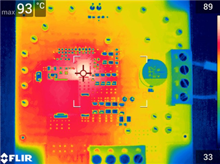
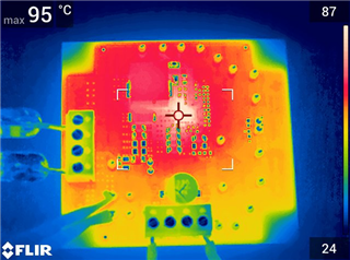
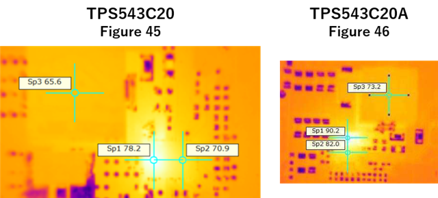
How much does TPS543C20A have differences in thermal performance including SOA from TPS543C20 (without suffix A)? I find that the values of the thermal metrics of the two devices in the data sheets are the same, but the thermal images in the section 11.3 show that the temperature rises are largely different. Besides, the SOA curves in the data sheets seem slightly different, too.

Best regards,
Shinichi Yokota

  • Hi SHinichi-san, 

    The TPS543C20A has a higher max recommended input voltage of 16V versus the TPS543C20 which has max of 14V. This higher voltage rating comes at a small trade-off in that the TPS543C20A has a slightly higher HS FET Rdson of 3.4mohm compared to the 3mohm HS FET of TPS543C20. 

    The SOA craves shows that small difference in thermals.  

    For the thermal images, the test conditions are not the same, the VOUT is difference from the two. The other thing I learned over experience, these thermal cameras are very sensitive to the test conditions such as EVM emissivity, distance from the board, horizontal Positioning, the calibration, focus, air flow...etc. Obviously, these two pictures are taken with two cameras types, with two different EVM's and who knows what the distance, the positioning , the calibrations, the focus, the room temps (LAB room temp at the time of the test) are? ...etc. So thermal images are good to give an estimate, but if you really want to do a comparison, you need to test them with identical  test conditions.   

    Thanks 

    Tahar

  • Tahar-san,

    Thanks for your quick feedback.

    For my reference, do you have measurement data that shows a difference in temperature rise under the same PCB condition?

    Best regards,
    Shinichi Yokota

  • Let me check internally if we have something we can share. 

  • Hi Shinichi, 

    We could not find the images. So we have take them on our EVM's.

    We will update you with the test results early Next week. 

    thanks!

    Tahar

  • Hello Shinichi, 


    Test Conditions are the same for both devices using the TI- EVM


    Vin = 12-V; Vout = 0.9-V; Iout = 40-A; Fsw = 500-kHz.


    We let the boards running for some time (Probably ~10 minutes) prior to taking the pictures.

    TPS543C20


    TPS543C20A

    Thanks

    Tahar