A related question is a question created from another question. When the related question is created, it will be automatically linked to the original question.
If you have a related question, please click the "Ask a related question" button in the top right corner. The newly created question will be automatically linked to this question.
my customer uses the TPS61088 device for car system ,it is required to test the Loop Compensation Test. would you kindly support this SCH review cases ?
Could you please share Vin range, Vout and load current for further review? If want to calculate Loop Compensation more accurately, pls also share part numbers of Cout or package, rated voltage of Cout. thanks.
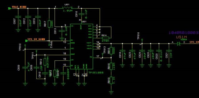
Vbat sch: If the chip is always EN by input supply, the EN pin can be pulled up to VCC pin because VCC is more stable than Vin. The current comp will lead to very high bandwidth and poor phase margin. It is recommended to change Rcomp to ~20k and Ccomp to ~4.7nF. I cannot see ILIMT resistor clearly because it covered by silk value, please set this resistor based on input peak current value.
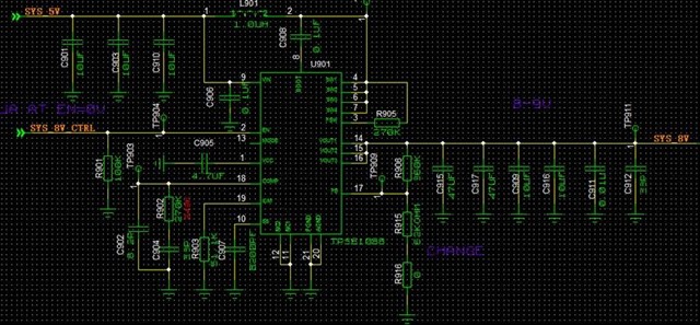
System sch: Also The current comp will lead to very high bandwidth and poor phase margin. It is recommended to change Rcomp to ~20k and Ccomp to ~4.7nF. I notice the ILIMT resistor is 51k, if so, this value may beyond the recommended range. Customer can change it to 100k.
would you share the excel formulas to me? it is a little difference between your recommendation and Webench design. And i also attach the excel file ,kindly check this ~
and what s the recommend value of the C808 and C902?
Customer can refer to this excel to calculate and the little difference will not effect the control loop very much. I think the little difference is because of effective output cap which is used 114uF in excel, in real application this value should be smaller according of DC bias.
C808 and C902 effect is not as important as Ccomp and Rcomp. Customer can use small value ~dozens of pF first and adjust them in real bench test. Typically we just leave this space in case of need, you may find in many EVM design this cap is NC as well.
Recently i check the loop test, after change the Rcomp and Ccomp as you mentioned. i want to sync up with you some confusion that the Vbat sch is still work abnormal, do you have any suggestion? tks in advance.
System 5Vin->8.2Vout/2A:(without changing Rcomp to ~20k and Ccomp to ~4.7nF)
Vbat(2.5~4.2)Vin->5V/2A(changing the Rcomp to ~20k and Ccomp to ~4.7nF)
Both two bode plots look strange, could you please check whether the wire connection or measurement is correct? The bod plot should be similar to the calculated one in the excel tool. Or maybe you can use another DCDC EVM to check the connection first.