This thread has been locked.

If you have a related question, please click the "Ask a related question" button in the top right corner. The newly created question will be automatically linked to this question.

TPS40210 Output Voltage Setting

Other Parts Discussed in Thread: TPS40210, LM317

Hello,

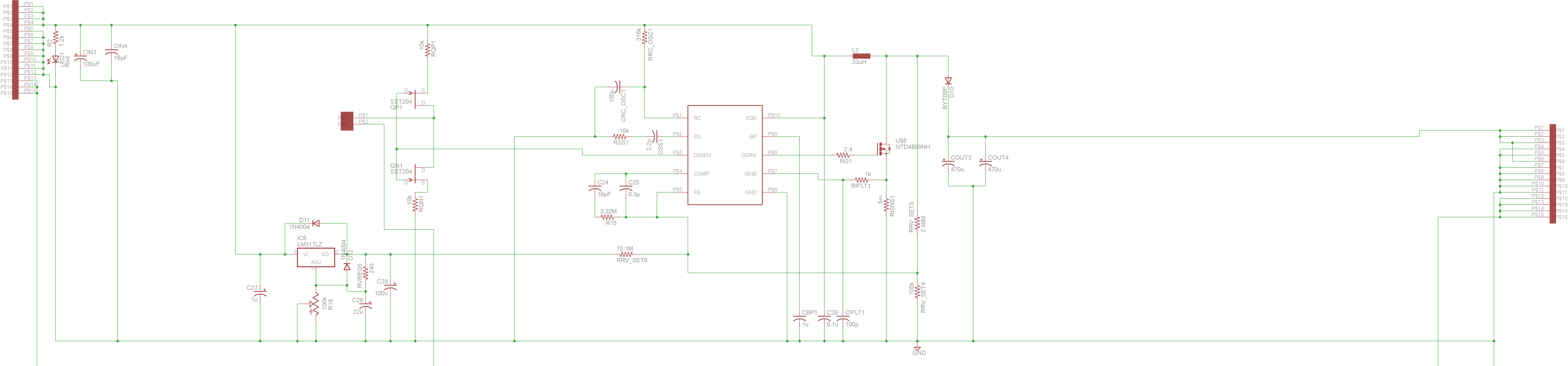
I am trying to design a boost regulator circuit using the tps40210 and am having some problems with the circuit that I constructed. In the datasheet there is some mention that the resistors in the voltage divider network should be chosen with two considerations in mind: low power consumption and noise.  Obviously, choosing large valued resistors will decrease power consumption but will large value resistors also make the circuit more vulnerable to noise?  I have chosen quite large resistors and am having problems with my circuit.  It will switch for awhile when I am measuring the voltage of the FB pin using a multimeter but as soon as I pull the multimeter leads off, the circuit stops switching.  Also, the measured voltage at FB is 0.5V instead of the expected 0.7V.

I am attempting to make the output voltage controllable by injecting a regulated voltage at the voltage divider midpoint.  I'm not totally sure if this can be done but I've seen it used with other topologies.

Please let me know if the problem I am having is due to large resistor values and if my approach of injecting an adjustable voltage is appropriate.

Thanks for your help,

Neal

  • I'm sorry, but your schematic didn't come through very well and I cannot read the resistor values.  You could repost as a pdf file.

    Yes, you can change the output voltage by adding a signal to the FB pin.

    I would keep your resistors at 10k or less for your circuit.  You are not able to measure the FB pin with a multimeter as this adds capacitance and resistance to this very sensitive analog input.

  • 2350.Boost_reg_layout.pdf

    Chris thanks alot for your reply to my post. Why do you think that the added capacitance to the fb terminal actually causes the circuit to switch and behave as designed?  Without the multimeter probe terminals connected to the fb pin there is no activity at all from the boost converter...  I suspect that this may have something to do with the huge resistances that I am using.  I have attached both a png and a pdf for your perusal. 

  • Yes, 15M and 2.5M is too large for this circuit.

    The FB pin is very high impedance.  When you add capacitance (and also about 1M to 10M of resistance depending on the input resistance of the multimeter), you create a somewhat lower impedance path for the signals.  At your high impedances, circuit parasitics dominate and the circuit no longer behaves as expected.

    Also, your compensation network is far too high impedance.  A 0.3pF cap will have more capacitance from the etch on the board than from the cap itself.  So, your circuit will not behave as expected.

  • Dear Neal,

    First of all, I agree with Chris. The feedback resistors are way too big. You should place also a capacitor on FB pin.

    Second: I do not agree with your FB connection. If I were you, I would have taken it after D10. In your case, you insert in FB all the pulses from the coil... Definetely you need the capacitor on FB. If you take teh feedback after D10, you may not need it - have a check.

    Third: LM317 - you want to add an offset, or what is it for? I do not consider it a failure, it has to work, but do you realy want it?

    If you want to keep your current consumption low, LM317 is not the best solution... You have also an LED on input. So, why do you worry to have a low-impedance on FB pin?

    The current you loose through the feedback resistors is way below the current you loose with the LED...

    I am very interested how did you implement the 5mOhm resitance. This should be quite tricky I assume. I never used so low resitors...

  • Ah, yes.  Thank you Paul for noticing the improper FB connection.  That voltage divider needs to be connected to the output voltage, not the switching node of the converter. 

  • Hello Paul and Chris,

    Thank you very much for your extremely helpful feedback.  I just had the chance today to re-design my circuit to implement some of the changes that you mentioned.  The goal of my design is to be able to adjust the converter's output voltage from 14.5V (when the lm317 has a voltage of 11.5V) to 19V (when the lm317 has a voltage of 0.5V).  To accomplish this I made the following changes:

    Compensation Network:

    C24 = 2n (previously 16p)

    C25 = 33p (previously 0.3p)

    R15 = 33k (previously 3.32M)

    Resistive Divider Network:

    RRV_SET4 = 1k (previously 100k)

    RRV_SET5 = 24k (previously 2.49M)

    RRV_SET6 = 62k (previously 15.1M)

    Now my circuit operates nearly EXACTLY as designed except with one problem: when the power is switched off to the circuit and then switched back on, nothing happens.  It isn't untill I play with the pot a bit that the switching actually begins...  I wondered if the circuit was unstable at that particular input voltage from the lm317 but it is not the case.  After I've gotten the circuit switching again I can bring it back to the previous lm317 voltage and the circuit works fine.  Just a problem when the circuit is switched on...   Any insights?

  • Neal,

    I guess that after you turn off the SR you try immediately to turn it on, right? Like 10 sec or less.

    Well, if I correctly read your schematic, you have a 100uF capacitor on LM317. This will hold the line a while.

    I bet with you that if you wait let's say 5 minutes and you turn your system on, it will start without problems.

    You have 2 possibilities:

    1. Remove LM317

    2. Decrease C28 down to the lowest value specified (100nF..1uF) and redo the test.

    I assume that because C28 is big, you will have a residual voltage on FB pin. This will stop your SR until C28 is discharged. Playing with the pot discharges the cap faster.