This thread has been locked.

If you have a related question, please click the "Ask a related question" button in the top right corner. The newly created question will be automatically linked to this question.

Noisy when BQ24650 is designed for 50W

Other Parts Discussed in Thread: BQ24650

Hello,

I was designing a Solar MPPT charger for 12V SLA battery using BQ24650. I was testing using electronic load since I don't have compatible Battery.

When I was doing on 20W, thw noise sound is low. But, when I designed for 50W to charge a 12V SLA battery with max charging current 4A, the noise sound is very loud when the battery voltage is less than 9V, meanings that while charging at precharge current regulaion phase.

It would be very appreciated if someone can share me experience on BQ24650.

  • Noise could be caused by various components, especially ceramic capacitors, vibrating due to control loop instability.  We have seen electronic loads cause the charger to become unstable.  Do you have a different electronic load?  Have you tried it with a battery?  Did you modify TI's bq24650 EVM or produce your own board?  Can you provide an oscillscope of the voltage across the output capacitor when you hear the noise?

  • Hi Jeff,


    Thank you for your prompt reply.

    (1) No, I didn't use EVM. I produced a new 2-layer PCB. But I strictly followed the PCB layout instructions as mentioned in application notes.

    (2) First, I produced a 20W board to charge a 12V/5AH SLA battery. When I was testing with battery no noise is there. Only when I tested with electroinc load I can hear the noise. The    scope image for output cap is attached.

    (2) Then I used the same PCB foot print for 50W board. I set MPP voltage as 27V and tried to test with electronic load. Setting of electronic load is 18V, since I am trying to charging to 18V battery. Once the charger is charging in Fast Charge Current Regulation Phase, noise is not there. But the PCB heated. Once I set the load voltage to 16V I can hear a loud noise.

    (3)I guess there is PCB layout issue and Inductor rating. But I would like to confirm.


    Thanks and Best Regards,

  • Is the ripple voltage actually close to 2Vpkpk? 

  • More than that. It is always around 4 to 6V pkpk.

  • That is a bit to high.  Are you certain that the inductor you choose is appropriate for your application?  The datasheet equations on page 21 can help size the inductor and output capacitor for your application.

  • I just followed the suggestions in SLVA437. I want to develope a board to charge a 18V SLA battery using 27V panel (since I cannot use supply beyond 28V). Here are the modifications I made.

    (1) I changed VMPP_SET programming resistors to be compitable to 27 V input.

    (2) Changed the VFB programming resistors to be compitable to 20.25V Buck voltage for 18V battery and followed the modifications in SLVA437 so that to match the battery's thermal characteristics.

    (3) Since input voltage is 27V I changed the MOSFET to Si7960 (VDS rating 60V).

    (4) Since the charging current is programmed as 2A, I used the same output capacitor 11uF and output inductor 10uH.

    Now I assumed that Eelctronic load may the reason for the noise. Because, even with EVK I can hear a low noise. Issue is the PCB heated. Due to my requirements, please advise me how should I modify to charge a 18V battery.

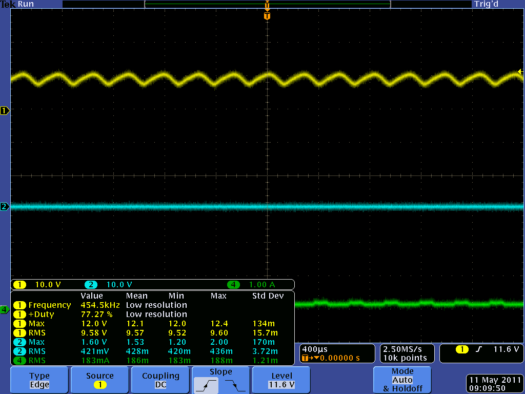
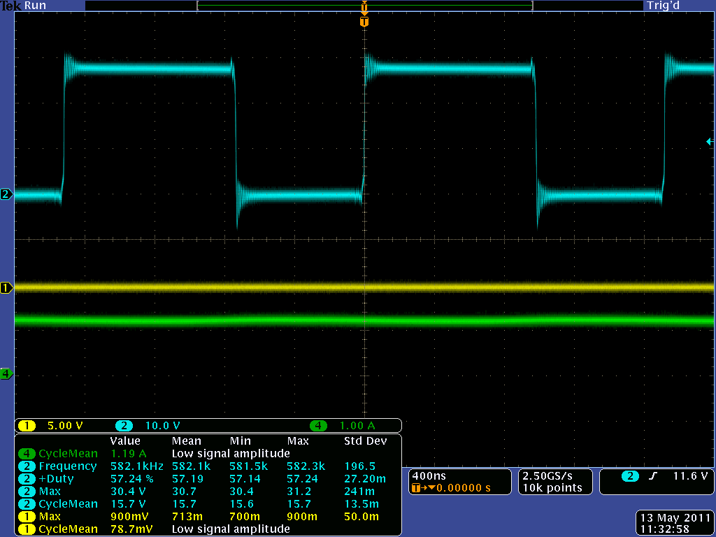
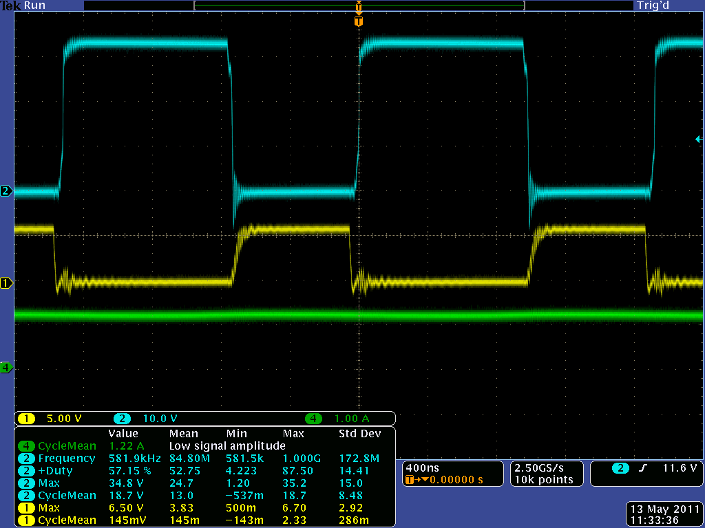
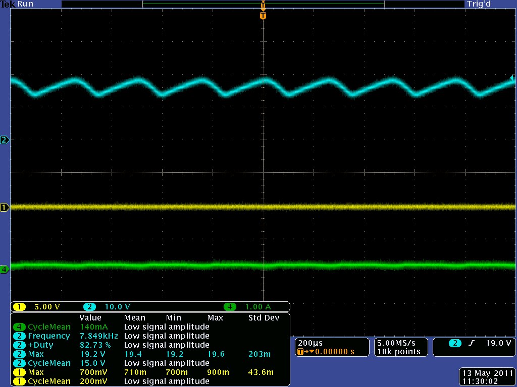
    Here I attached the scope images for Vout ripple when I hear the noise, PH node voltage wave form while charging current is about 1 9A and MOSFET gate voltage waveforms while charging with the same current.


  • Yes, the electronic load may be causing instability.  I recently had the same problem with another battery charger IC.  Can you test with a battery? 

  • Hey Tin TIn,

    Are you still around. I posted a similar problem and I was wondering if you found a solution. 

    Gary