This thread has been locked.

If you have a related question, please click the "Ask a related question" button in the top right corner. The newly created question will be automatically linked to this question.

LM5170EVM-BIDIR: IOUT1 minimum measured current

Part Number: LM5170EVM-BIDIR
Other Parts Discussed in Thread: SFRA

Hello,

I am using LM5170EVM for solar application. My power demand is input voltage 35 V output voltage 40 V and input current 2.2 A boost operation. For MPPT control, I would like to sense current minimum 0.2 A of current from Inductor from IOUT1. The evaluation board is tested with power supply as input voltage and resistor as output load in open loop without analog based outer voltage loop compensator, also channel 1 Enable pin is turned off. The output voltage in the case as said above will be equal to input voltage with diode forward voltage drop. As, the body diode of high side MOSFET conducts, thus with power supply in constant current source. 

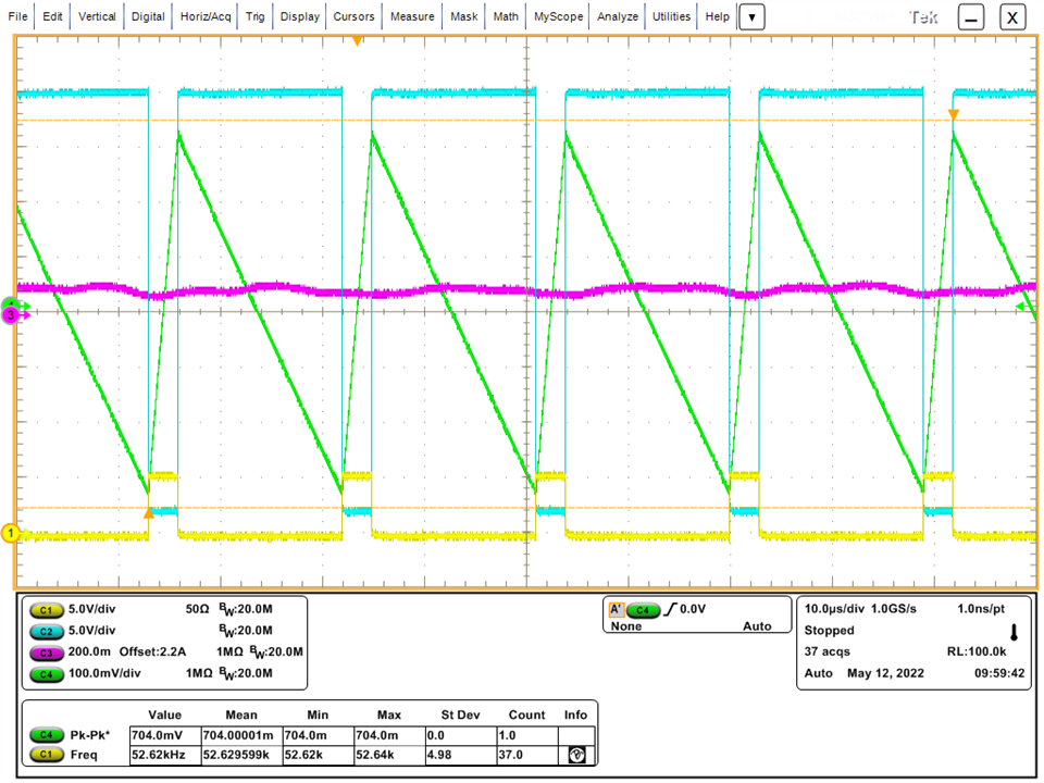
With injecting current in the system, while monitoring IOUT1 in scope:

Under 0 A -> IOUT1 voltage 230 mV

from 0 A to 0.55 A IOUT1 voltage 230 mV

0.6 A IOUT1 voltage 231 mV

0.7 A IOUT1 voltage 235.7 mV

0.8 A IOUT1 voltage 240 mV

Is there any method for measuring/ calculating current between 0 A to 0.55 A?

Thank you

  • Hi Jeet,

    Thank you for posting.  if your working current is just up to 2.2A, you will need to increase the current sense resistor from 1mOhm to at least 20mV to increase the working signal amplitude to make the IOUT monitor more accurate.  The EMV's 1mOhm resistor is chosen to work for up to 50A's application. In your application, the current sense signal is too low and the errors become more pronounced.   Change Rcs and use the same equation given in the datasheet to get the actual current info.

    Thanks,

    Youhao

  • Hello Youhao,

    I have changed the sensing resistor from 1 mohms to 5 mohms to increase the IOUT1 resolution for the system.

    Also, prior to the change I had set my switching frequency to 160 kHz and inductor used was 33 uH. 

    Rosc is 25 kohms and Rramp1 is 61.9 kohms.

    After changing the sensing resistor, I witness a decrease in switching frequency for MOSFET from 160 kHz to 53 kHz. Please find the attachment below. 

    Channel 1 - High side MOSFET drain to source voltage

    Channel 2 - Low side MOSFET drain to source votlage

    Channel 3 - Input side DC current

    Channel 4 - Inductor AC current (ripple current has been increased due to decrease in the switching frequency) 

    Prior the ripple current for 33 uH inductor and 1 mohms sensing resistor was less than 1 A.

    Currently after changing the sensing resistor from 1 mohm to 5 mohm, the ripple current is 3.5 A, thus system is operating in diode emulation mode.

    Why did switching frequency decrease due to change in sensing resistor?

  • Hi Jeet,

    Basically Rcs has no effects on the oscillator frequency. Please monitor SYNCOUT signal.  If the frequency is still 53kHz, then double check your OSC resistor.  It may be a wrong value or soldering problem.  Replace it with a new resistor. 

    Thanks

    Youhao

  • Hello Youhao,

    The oscillator frequency is 158 kHz from SYNCOUT signal. But as shared the attachment above, the MOSFET are switching at 53 kHz, is there any other component/ parameter which changes the MOSFET switching frequency?

    Also, the ripple current 3.5 A shows similar results with simulation at 50 kHz switching frequency.

  • The above shared attachment is for an unstable output voltage. Recently, I tested the converter for a stable output voltage at 42 V with 35 V input voltage. Please find the attachment below.

    Channel 1 - High side MOSFET drain to source voltage

    Channel 2 - Output voltage

    Channel 3 - Low side MOSFET drain to source voltage

    Channel 4 - Inductor AC current (ripple current has been increased due to decrease in the switching frequency) 

    The ripple current is 2.5 A and the switching frequency is 79 kHz. 

    Currently, the sensing current resistor is 5 mohms.

    oscillator as seen at SYNOUT is 158 kHz

  • Then, this makes me worry about your circuit skipping pulses for some reason that we yet to figure out.  Could you try to reduce the load current and see if this is still the case?  

    Please also monitor ISETA, COMP1, COMP2, along with the inductor current.

  • Hello Youhao,

    Good morning 
    Few descriptions regarding the use of convertor and results as shown above. I am using the convertor without analog voltage loop compensator and providing the control signal via external microcontroller.

    The input voltage is 35 V

    Output voltage is 40 V

    I am utilizing only channel 1 of the system.

    ISETD is 14% duty with frequency 100 kHz

    The inductor used in the power stage is 33 uH

    I have updated the inner current loop Ccomp, Rcomp and Chz. 
    The oscillator switching frequency ks set to 160 kHz

    At output end the power is sinker via electronic load with constant resistor of 22 ohms.

    Input power is supplied using DC power supply.

    Will monitor Voltage at Ccomp1

  • Hi Jeet,

    Any update on the test?  I think your setup is not correct.  You E-load should be in CV mode at your targeted 40V, otherwise you create conflict, because 22 Ohm would create a higher voltage at about 82V when your ISETD is 14% duty, not what your desired 40Vout.  

    Thanks,

    Youhao

  • Hello Youhao,

    Good Morning,

    Last week, I successfully run the DC-DC converter in boost mode. The solution to issue discussed in previous chats were:

    After changing the inductor to 33 uH, increasing the sensing resistor to 5 mohms and increasing the switching frequency to 160 kHz, the inner current control loop was not stable. And so to achieve CCM operation with input voltage ranging from 10 V to 38 V with output voltage 40 V and minimum power of 24 W, the RC network for the inner current control loop was updated to achieve higher bandwidth and stability. 

    Currently, the RC network consists of:

    Rcomp 4.7 kohms

    Ccomp 47 nF

    Chz 100 pF

    With converter being stable and in CCM mode, currently I am working on implementing SFRA by TI, to obtain the close loop response of inner current control loop. 

    I am using ISETD (Frequency 100 kHz) as control signal with small signal injection in ISETD. 

    A new issue has been reported, With sweep the ISETD with small signal injection, I noticed an decreasing in amplitude at MOSFET drain to source.

    I have attached an image for better explaination


    The duty given to the control signal has an equal variation in duty due to small signal injection at the frequency range range specified in SFRA. But, while observing the duty variation in gate to source of MOSFET, I noticed that the duty variation isn't consistent and decreases with increase in small signal frequency.

    I would like to understand whether ISETD is not compactible for implementing SFRA and should I be using ISETA for SFRA implementation.

    Please let me know if the issue asked is not clear.

    Thank you for the replies. It does help.

  • Hi Jeet,

    This may be related to the delay time of converting ISETD to ISETA.  The internal 100k resistor and the ISETA capacitor forms a low pass filter and it may be too slow to respond to your high frequency sweep.  

    I would recommend you to ground ISETD and use two RC-RC stage to achieve the PWM to ISETA conversion, in which you can minimize the delay.

    Thanks,

    Youhao