This thread has been locked.

If you have a related question, please click the "Ask a related question" button in the top right corner. The newly created question will be automatically linked to this question.

TPS61090: Power management - INTERNAL forum

Part Number: TPS61090


Hi,

Customer Kohler asks:  

Recall several months ago TI helped Kohler understand why a TPS61090 was having oscillation problems. It was due to too low ESR on the bulk capacitance.  Recently Kohler updated the schematic to the following (C20 was previously 100µF, however due to design change now need more energy stored at 5.5V in case power is lost):

New C20: UVR1A222MPD

Previous C20: TPSD107M016R0150

C3: EMK107BJ225KA-T

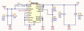
Kohler is trying to ensure this design meets the datasheet’s ESR requirement.

The concern is that the EMK107BJ225KA-T and UVR1A222MPD in parallel may result in an ESR below 30mOhms.

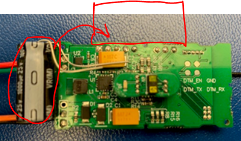
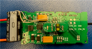
Additional concern is in this design, the bulk capacitor C20 cannot be located nearby the TPS61090 due to physical space constraints. The image below shows the bulk capacitor planned location. You can see the location of U1 is between the yellow tantalums present on the previous prototype board.

Can you help Kohler understand if the design will be stable and how to best determine or evaluate?

Thanks,

HSG  

  • Hi HSG,

    Thanks for your questions. Please kindly see my comments below.

    Q1: The EMK107BJ225KA-T and UVR1A222MPD in parallel may result in an ESR below 30mOhms but it may not cause unstable except ESR is very small like less than 1mOhm, then it will need the forward capacitor to compensate the loop.

    Q2: It's OK that the electrolytic capacitor is a bit far from device. But the C3 must be put close to Vout pin of TPS61090.

    Regards,

    Bryce

  • Hi Bryce,

    Thanks for the help.  Customer is still trying to understand further.  I have asked them for their estimated effective ESR.   However can you comment any further as they are unsure how to further evaluate?

    The wording used was “may not cause unstable”. What conditions might it become unstable?
    I want to ensure the components I am selecting are acceptable from a design perspective for this regulator.

    How will I know if I need the forward capacitor?

    Also the capacitor does not have the opportunity to be located on the side (in the red box). There are severe location constraints in the design which set it up to only be located at the original location shown in the image.
    What is the consequence of locating C3 in its current location?

    Thanks,

    HSG  

  • Hi HSG,

    The effective ESR almost equals to the paralleled value of ESRs. For example, ESR1=150mohm and ESR2=6mohm, the effective ESR almost equals to 150*6/(150+6)=5.8ohm.

    As my college reported before, if four ceramic capacitors are used, the effective ESR would be 5mohm/4=1.25mohm. It was proved to be unstable with experiment. And at that condition where the effective is very small, the forward capacitor is needed.

    The present selection is effective ESR=6mohm which is similar to my college verificated before, effective ESR=5mohm and it's stable.

    I don't see the C3 location on the pic clearly. Pls follow the recommend layout shows below. Put the 2.2uF cap close to Vout pin. Otherwise, it may cause large spikes on SW.


    Regards,

    Bryce