This thread has been locked.

If you have a related question, please click the "Ask a related question" button in the top right corner. The newly created question will be automatically linked to this question.

UCC27531: Ferrite bead at output

Part Number: UCC27531

Hi All,

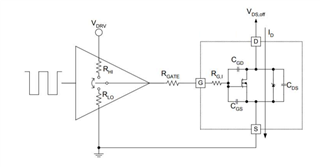
we are using UCC27531 as digital output driver. Input of UCC27531 is driven from MSP430.
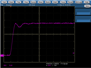
when we put a ferrite bead at the output the signal gets distorted please see the scope shot.
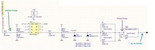
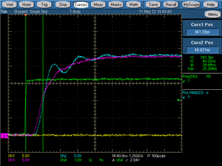
how to proper choose the FB?
Best Regards,
David.
  • Hi David, 

    Thank you for your question. Our expert is out of office today and will get back to you by tomorrow. 

    Best regards,

    Leslie

  • Hi David,

    Thank you for reaching out on E2E!

    Can you please confirm that these scope shots are taken with the tip and barrel method?

    If using the tip and barrel method does not remove the signal distortion you are seeing you can refer to this E2E FAQ and Application brief that I will link below regarding the use of ferrite beads in gate drive circuits.

    If you need further assistance please reach back out!

    Thank you,

    Kevin Kosta

  • Hi Kevin,

    the green signal is measured with active probe, and i remeasured the signal after ferrite bead with tip-barrel method and it doesn't remove the signal distortion.

    this signal is digital output , 100Hz with on time 30us. I read your application notes, but i don't understand why would a FB distort a signal?

    How can a Ferrite bead cause noise peaking?

    Best Regards,

    David.

  • Hi David,

    Thank you for reaching back out!

    The small ringing that you are seeing I believe is not from the ferrite bead, but could come from a couple of things on the side of the MOSFET:

    • Parasitic capacitances from Cgs and Cgd  and parasitic inductance creating a RLC resonance which causes an oscillation 
    • Parasitic inductances from long trace length and/or poor PCB layout 

    You can also take a look at this Tech note that goes into more detail about these effects from the FET

    You can also experiment and remove the ferrite bead and test different resistor values to see if it dampens these effects

    If you need any further assistance please let me know!

    Thank you,

    Kevin

  • Hi Kevin,

    that is the thing i don't have a mosfet after the ferrite bead. please see schematic that i provided previously.

    if you look at my first scope shoot, before ferrite bead ( purple signal is as it should be), and after the ferrite bead i see oscillations ( blue signal).

    This is a push-pull output from a device, and i don't have any load connected to it, only a scope probe. 

    Br.

    D.

  • Hi David,

    Sorry for the misunderstanding on my part!

    Out gate drivers are made to drive capacitive loads from FETs. Can you clarify for me the application you are using this for?

    Ferrite beads share some similar characteristics with an inductor. You may be seeing some LC resonance created by the ferrite bead in conjunction with the capacitors in your design.

    Can you please send the full schematic to me? This is a public forum so please send me a private message request so I can further help!

    Thank you,

    Kevin

  • Hi Kevin,

    this is the full schematic, the CAM_TRIGGER_OUT signal connects to MSP430 output pin, and after the ferrite bead there is a connector to outside world

    Also we can continue here if you wish, otherwise i will send PM.

    Best Regards,

    D.

  • Hi David,

    Thank you for sharing this with me!

    Can you please answer a few more questions for me? This way I can better assist you!

    1. Can you please tell me what the application is here?
    2. Is there a slew rate requirement?
    3. Is the small wave you are seeing with the blue probe a concern for your application?
    4. If it is a concern, can you please tell me why it is a concern?

    Again if you do not feel comfortable sharing on here please send me a private message.

    I look forward to hearing back!

    Thank you,

    Kevin

  • Hi Kevin,

    sorry for late replay.

    1) this signal (signal is a trigger signal) is generated on our device ( MSP430 MCU generates this signal) , and it goes out of the device through a  connector.

    The signal connects to a camera via cable to trigger the camera.

    2) The signal shouldn't  have overshoot 

    3) i don't think that is a big concern, we will have to test it.

    But what i don't understand if a connect the signal that comes from UCC27531 output to a ferrite bead then i get this noise after the ferrite bead and befor the ferrite bead ther is no noise ?

    Because in this app-note SLUAAI2, the ferrite bead should suppress noise when used with gate drivers and not introduce.

    Best Regards,

    David.

  • Hi David,

    No worries thank you for getting back to me!

    I believe that the ferrite bead is still doing its job of suppressing noise as indicated by the purple probe protecting the gate driver. It looks like the output of the driver after the ferrite bead is going into a ribbon cable. I assume that the ribbon cable is long in this case. Because of that, there is going to be parasitic inductance introduced. The noise you are seeing is probably coming from the ribbon cable.

    One way to reduce this would be to introduce another ferrite bead at the other end of the cable connection. If the noise still seems to be a concern for you I would try that. 

    If you need any further help please let me know!

    Thank you,

    Kevin