This thread has been locked.

If you have a related question, please click the "Ask a related question" button in the top right corner. The newly created question will be automatically linked to this question.

BQ76952: Current consumption during balancing process

Part Number: BQ76952

Dear,

I am working the balancing process on our project with the BQ76952. I have some doubt regard consumption.

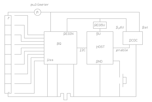
First, my architecture is BQ76952 (using I2C) on a 8S4P LIion battery. No Reg0 used. Powersupply is with external DCDC managed by the host processor. Host is also powered by the DCDC; REG1 and REG2 are not used for external thinks.

When I switch off the DCDC (REGIN became off), I can measure the battery current consumption at arround 280uA in nominal mode.

In case of the balancing mode is active, when I switch off the DCDC, the consumtion is arround 1,5mA (why?)

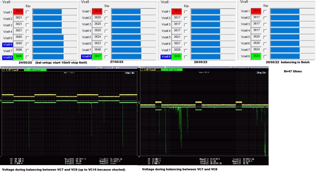
At the end of the balancing process (saw because no heating detected on Vcell serie resistors), the current still at 1,5mA.

Do you have any reason why the consumption during balancing is x5 the nominal consumption and why this consumtion stay high after balancing process.

The plan is to enter in shutdown mode if no balancing procees active and when I switch off the system but if balancing is active, I keep the BQ working because is a very long process.

However, the consumtion is 1500x higher than shutdown and I don't want that the system keep discharging the battery if the system is off during some month.

Any information is welcome

Best regards

Thierry

  • Hey Thierry,

    Where are you measuring the current? Also I'm not sure I understand your application. You have a DCDC converter output on the REGIN pin, but you aren't using REG1 or REG2? Can you elaborate?

    Thanks,
    Caleb

  • Hi Caleb,

    I am measuring current on the positive battery cable with an Agilent U1252A. Here picture resuming the system.

    I need up to 1A current for several functionnalities. So, for that I am using an external DCDC.

    True, REG2 is always off. REG1 is Enable and set to 5V for some pullup resistor and BQ internal digital level references need for Host interface.

    When I switch off the system in normal conditions, the host generate the >1s pulse for shutdown the BQ and then switch off the DCDC. Then, I=1uA.

    But in case of balancing active, I switch off the DCDC without the shutdown pulse. The BQ still working with 1,5mA consumption.

    For check the BQ consumption in normal mode (when not balancing), I have done a special code for switch off the DCDC without shutdown pulse and in this case, the consumption is 280uA.

    My doubts are:

    - is 1,5mA consumption normal when BQ is balancing (instead 280uA in nominal work)?

    - Why BQ still have 1,5mA consumption when balancing is finish.

    Hope it is more clear for you now.

    BR

    Thierry

  • Hey Thierry, 

    That did help clarify. I have some more questions for you.

    Are you using internal cell balancing or external cell balancing? Is your cell balancing host controlled or autonomous?

    Device specifications state that each cell balancing uses 35uA. So 1.5mA current draw is not normal.

    Thanks,
    Caleb

  • Hi Caleb,

    I am using internal cell balancing with 56R resistors. Balancing is autonomous.

    The worst case for 8 cell is 4 cells balancing (as I set 4 cell max). So, 140uA.

    Tomorrow I will try with another board in case of something is damage on this one.

    BR

    Thierry

  • Hi again Caleb

    I try more board and they are worst. Current draw during balancing is 2,2mA

    Any idea?

    Th

  • Hi Thierry,

    Can you measure across the different resistors on your board to track down where the current is flowing? From my understanding REGIN is 0V in this state? Can you describe which connections have resistors to REG1?

    Regards,

    Matt

  • Hi Matt,

    I have a 100R serial resistor with BQ Bat input and here, I can see the 1,5mA (I back with the first board).

    See on picture the both voltage. Delta=155mV for 100R so, 1,55mA.

    REGIN=0V

    No resistor in REG1, only a capacitor. REG1 is for internal digital level reference only.

    I check on all resistor (mosfet's gate, load, pack, I2C pullup) and nothing draw here.

    The board was working 24H balancing. balancing R are cold and cell are now on equalized but current draw still 1,5mA.

    I would like to remember that if I switch off the external DCDC without shutdown request, the current draw is 280uA.

    Only I have this extra consumption if I switch off with balancing mode activated and even balancing stop at the end of process.

    BR

    Thierry

  • Hi Thierry,

    I see a couple of issues in the schematic:

    • The REGIN capacitor should be 22nF. See the datasheet spec below:

    • There should be a cell connected between VC16 and VC15. I think this could be related to the issue you are seeing. See the Unused Pin Table in the datasheet for instructions for the unused VCx pins and the video link below for more description. The internal balancing FET between VC16 and VC15 is different (P-FET vs. NFET for the other pins) because otherwise it would need a voltage higher than VC16 to turn on.

    https://training.ti.com/creating-schematic-bq769x2-battery-monitors 

    Best regards,

    Matt

  • Hi Matt,

    I change the REGIN to 22nF value and, as expected, there is no change. In fact, REG0 is disable and I imagine that this 22nF is importante for the regulation of REG0 using the BJT.

    Regard the VC16/VC15 cell, it is clear that I missed this topic on the datasheet.

    However, I check on the BQ76952EVM the same config using Vcell from 0 to 8 and I check the current draw on Bat pin measuring the voltage drop on the 100R resistor.  I found 1mV so 10uA. Include in nominal mode when I must have arround 280uA. I must check deeper why this difference.

    I understand why the mosfet between Vcell16 and Vcell15 must be P-FET (due to gate level), but I don't understand why we must used the Vcell16/Vcell15. May be I must accept it because datasheet say it. May be the datasheet and the "Battery management studio" must also specify that "Vcell mode" must have bit 0,1 and 15 set to "1".

    As I can't reproduce the problem on the demo board, I have not clear if my problem is this.

    I also still not understanding why the current draw still arround mA despite the balancing is finish and why after a reset everything became ok .

    Best regards

    Thierry

  • Hi Thierry,

    Just to clarify, is the extra current only observed when the balancing is enabled in the BQ76952 registers? If it is also present when balancing is disabled, the extra current must have a different cause. 

    Matt

  • Hi Matt,

    I still looking for this topic with the demo board. I just make more test on the EVM board and I measure on the 100R resistor arround 260uA in nominal work and also balancing. I have connected the 8 cells same as my board so, from Vcell0 to Vcell8. Then I have made bridge between each no used Vcell input.

    Conclusion, it seems not because I am not using Vcell16/15.

    To answer to your question, and clarify the situation: My firmware generate the BQ shutdown pulse when turn off is requested by the user when balancing is not active (AlarmRawStatus bit2 = 0).

    If turn off is requested and balancing is active ((AlarmRawStatus bit2 = 1), the DCDC is disabled but the BQ shutdown pulse is not done to keep balancing working. In this case, current draw on the 100R resistor is 1,5mA (up to 2mA on other boards).

    I have bypassed the shutdown pulse on my firmware for test current draw for keep the BQ in normal mode. I found 280uA as normal conditions.

    For another side, checking things on the EVM, I saw something very strange. In fact, loading thes attached file on the EVM, I have 3,3 V on the REG18.

    I don't reach to find where was the failure on this file.       _test3.gg.csv

    To be continued...

    Have a good week end

    Thierry

  • Hi Thierry,

    I don't think it is possible for the REG18 pin to show 3.3V - is there a chance you are measuring a different pin by mistake? 

    When I reviewed your settings, I notice that some of the general purpose digital pins are set to drive the REG1 voltage when they are high. Since you have REG1 disabled, I wonder if this could be causing any current draw somehow.

    Regards,

    Matt

  • Hi Matt,

    I found the problem. In fact, you are true, the Alert pin was set for be high when balancing. Also it seems that this pin is latched (using AlarmStatus mask) and so, it stay high despite balancing is stop. The problem was that Alert pn was set with REG18 level instead REG1 level.

     I must take care of this type of feature.

    Regard the 3,3V on REG18, it was not a mistake. I imagine that  any BQ output is set as with REG18 level and connected to host output at 3,3v. So, similar failure.

    Thanks for the support.

    Thierry

  • This topic is closed but I learn things about the BQ76952 use. One of these, I would like to evaluate the risk regard the use of Vcell input from VC0 to VC8 instead VC0 to VC6 and VC15/VC16.

    What could be happen with my actual configuration? Can I damage something and why?

    I am burn also soe mosfet during short circuit test and I think that switching off is not fast enough (4 parallel mosfet). I saw on the video an option for ncrease switch off when a lot of parallel mosfet.

    I am preparing a new pre serie batch so, it is important for me to evalaute the change asap.

    Thanks in advance and best regards

    Thierry

  • Hi Thierry, 

    I'm glad you were able to locate the issue on the Alert pin.

    The connection of VC0 to VC8 will not cause any damage, but the top cell will not be able to balance. For the protection FETs, switching too fast can also cause damage because transients can be very high. The Multiple FETs with the BQ769x2 document is the best reference for help choosing the gate resistor, charge pump capacitor, turn-off circuits, etc. https://www.ti.com/lit/an/sluaa09a/sluaa09a.pdf 

    Best regards,

    Matt

  • Hi Matt,

    Strange, during my balancing test I had the cell1 lower and it seems that all other was reducing voltage include the cell8 (top cell).

    I will test again.

    Regard FET, I will also read the sluaa09a document.

    Thank you.

    Thierry

  • Hi Matt,

    Here the balancing test result using VC8 to VC16 shorted and top cell between VC7 and VC8.

    Balancing is "working" but a quite less efficient on the top cell.

    In fact, for any reason, the duty cycle is not the same on the top cell than other. Also, the delta voltage is quite higher when mosfet short VC7 to VC8. So, less current draw.

    R are all at 47 Ohms. I can may be compensate a little bit changing the top resistance by a 22R (as I read on another thread) but I will never reach the same balancing performance. 

    Hope that this will also help BQ76952 users.

    Best regards. Thierry

  • Thanks for sharing this Thierry! We do not have internal test results where the top cell is not connected between VC16-VC15, so this is good information that I can share with other users in the future.

    Matt