This thread has been locked.

If you have a related question, please click the "Ask a related question" button in the top right corner. The newly created question will be automatically linked to this question.

TPS53511: Large output ripple

Part Number: TPS53511
Other Parts Discussed in Thread: TPS54226

Hello,

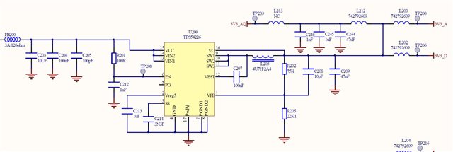
I am using the TPS53511 as an alternate solution to the TPS54226.

With the TPS53511, I have a large output ripple (about 80mv) on the 3.3V ouputs. See below.

The SW output waveforme is :

I do not have this problem with TPS54226 in the same conditions :

     - ripple voltage is  <10mV

     - the SW output is a stable PWM signal close to 700kHz.

Given the datasheet of both component, I do not understand why such difference and what needs to be tuned to get similar performance.

Thanks for your help and support,

Philippe.

  • Hi Philippe,

    TPS53511 is designed with auto-skip mode to increase the light-load efficiency. What is output current for your test? if the output current is lower than 1/2 inductor ripple current , the converter will go to discontinuous conduction mode, the switching frequency will reduce and output ripple will be higher. It is expected. Please double check.

    Hope this helps,

    Thanks,

    Nancy

  • Hi Nancy,
    Thanks for the input.  What surprise me is that, if I am not mistaken, both TPS53511 and TPS54226 follow the same rules. So I would have expected that both be in discontinuous mode. Anyway, I will check and post the results soon.

    Philippe.

  • Hi Phillippe,

    Thank you for your question. Yes both TPS54226 and TPS53511 should enter PFM or eco-mode when the output current is low enough. 

    The higher ripple is related to the multiple on-time pulses during the PFM operation. I need to check with design if the light load operation will be similar to that of TPS54226 or not but in most cases the expectation is a single on-time pulse followed by a larger idling time during PFM. For example, check figure 8-9 in another datasheet (click here)

    • Is it possible to share your schematic & BOM for this design that you are testing with? Do you have a custom board built for this?
    • Are you using an eload for this testing? If so, I would try with a resistive load as well.
    • What is the load current value and input voltage? 
    • I can review the schematic that you send but you may also benefit by adding a small feedforward capacitor in parallel to the top resistor of the FB divider network. A value between 10pF to 47pF may be a good start depending on the feedback resistor values.

    Thanks,

    Amod

  • Hello Amod,

    Here is the schematic. Hope this is readable... Let me know.

    This is a custom board initially designed with TPS54226. The input voltage is 12V. The 10pF is already included in the design.

    For the current, I will check early next week and post the answer.

    Thanks for your support.

  • Hi Philippe,

    The schematic looks fine as such. 

    • Can you possibly decouple the output from the ferrite bead network by removing L202 and checking if ripple across C200 is any different?
    • Please let me know about the output current as I want to check if the device will operate in PFM or PWM.
    • Can you try changing the Vin and Iout values to see if this behavior is consistently occuring or only occurs during certain Vin/Iout combinations?
    • Are you using an eload for this testing? If so, I would try with a resistive load as well.
    • You may try using a smaller inductor like 2.2uH/3.3uH and increasing the 10pF C208 to 22pF/47pF to see if the multiple pulsing goes away.
    • For the C200 47uF cap, do you have the voltage rating or the part number? Just trying to ensure there is enough capacitance post DC-bias derating.

    The device is relatively older and I do not have an EVM to work with so cannot confirm if the multiple pulses are normal or not (some devices do operate with multiple pulses during light load) but I expect a single pulse operation like the figure 8-9 in this datasheet (click here) Sometimes, design instability may cause this type of multiple pulse behavior.

    Thanks,

    Amod

  • Hello Amod, 

    Here is what I have :

    - the output current is 390mA.  I have tryed a 8.2 ohm resistor load and disconnect the actual load. Same result.

    - with exactly the same setup, same BOM, same layout ( and 8.2 ohm load), the TPS54226 operates in a different mode (continous PWM at ~700kl/s). While the 53511 operates as mentionned above.

    - disconnecting the ferrite beads and emulating the load with a resistor bring : no change as mentionned above.

    - the output capacitor (C209) 47uF is X5R 6.3V 0805.

    I did not have the opportunity to change the inductor or C208 capacitor.

    I will play with the resistor load and check the impacts.

    Comments welcome.

    Philippe.

  • Hi Philippe!

    Amod will reply you tomorrow!

    Shuai

  • Hi Philippe,

    Based on your description, it looks like TPS53511 enters PFM operation for the same condition under which TPS54226 stays in PWM operation. The devices are different internally so the parameters defining the switching frequency and thus the transition point from PWM to PFM may be different. Please try to check if you see the same behavior in PFM on TPS53511 across various Vin, Iout conditions. In the end, you may need to play around with inductor values to see if the ripple can be reduced. Finally, if ripple is a primary requirement, you may need to check other devices which stay in PWM mode or are in forced PWM mode across various conditions.

    Thanks,

    Amod

  • First, thank you for all contributors, Nancy and Amod.

    My last experiments show that :

    a) With TPS53511 and current design and operation conditions, the load current is very close to the switching point between PWM and PFM. If I add 3mA to the 390mA, then the regulator enters in PWM mode with much lower ripple.

    b) similarly, if I lower the voltage input to 10V, the TPS35511 enters in PWM mode.

    c) as pointed out, the behavior of the TPS54226 is quite different. And seems to offer much lower ripple in all conditions.

    So, I think I have an opportunity to use the TPS53511 but I need to make sure that it will stay in PWM mode in the full input DC range (9V-15V).
    Most likely, I will have to increase the inductor ( 5.6u ?)

    I am waiting your last comments (if any) and I will close the case.

    Thank you again.

    Philippe.

  • Hi Philippe,

    It is ok to increase output inductor.

    Thanks,

    Nancy

  • Hello, thanks. I close the case.