Other Parts Discussed in Thread: TDA4VM,
Hello,
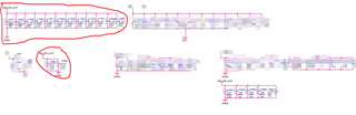
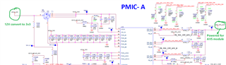
Currently we are trying to use the PMIC(TPS65941212) module for TDA4VM(Soc), we use BUCK1,BUCK2 & BUCK3 output for AVS module power supply as showed from below SCH:
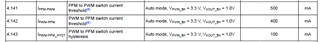
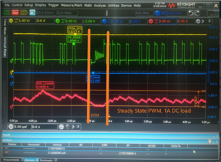
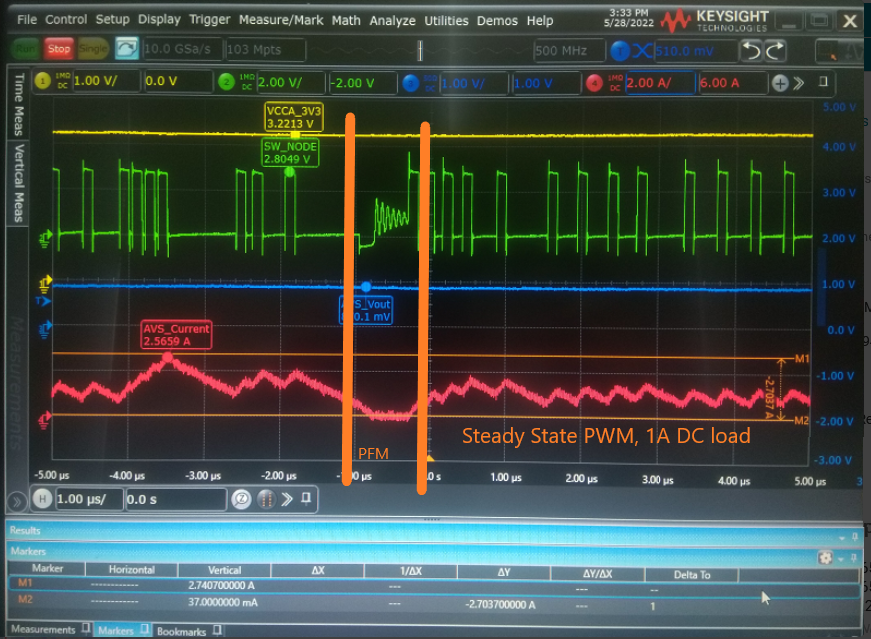
But we are confused for the power mode operation when we are performing some tests, At the beginning of TDA4 startup,The AVS load current is not high(Light load), the PMIC works on PWM mode operation,
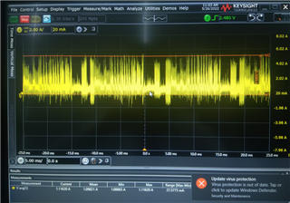
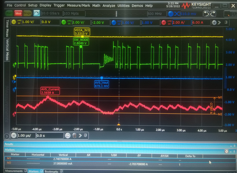
But after the AVS module works up(Heavy load), The PMIC we found it enters to PFM mode as below:
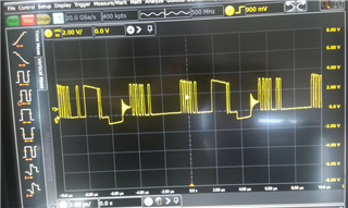
as far as i understand it should keep on PWM mode for heavy load when it set to automactic mode default, While it enters to the PFM mode, It cause the some Capacitance scream!!
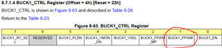
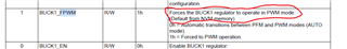
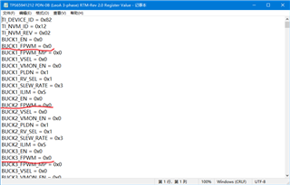
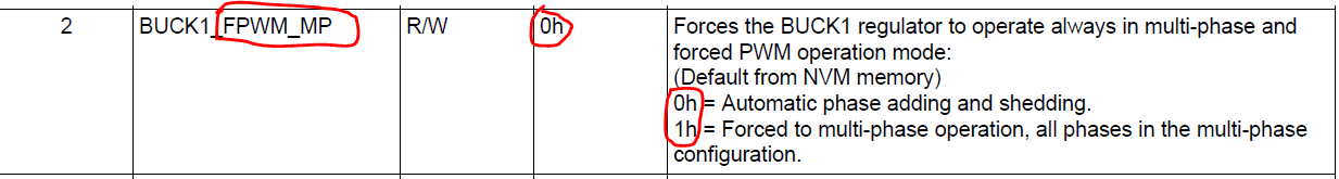
I do understand we can set the PMIC to FPWM through I2C by TDA4VM, Is there any other GUIs or drivers that i can try to set the PMIC mode default to FPWM not by TDA4(currently we are limitated by our software) ?
Thanks!