This thread has been locked.

If you have a related question, please click the "Ask a related question" button in the top right corner. The newly created question will be automatically linked to this question.

UCC28950: (UCC28951)Irregular C, D drive output

Part Number: UCC28950
Other Parts Discussed in Thread: UCC28951

Hi Team,

It is an application using UCC28950, and it is designed to be set as a slave and operate at a synchronization frequency of 190kHz from the outside.

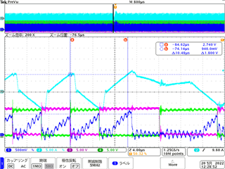
Often, there is a mode in which the High / Low time of the C and D drive outputs becomes long.

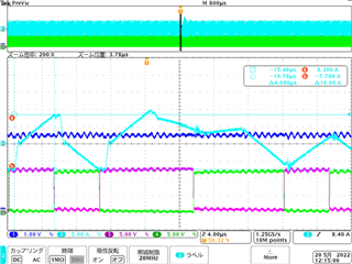
When I checked the threads in the past, I confirmed that the same mode occurs when the Duty is 90% or more and the overcurrent state occurs.

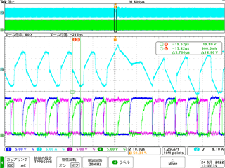
 I tried changing to UCC28951 as a solution, but this mode is still occurring.

Please give us some advice on the cause and solution of this mode.

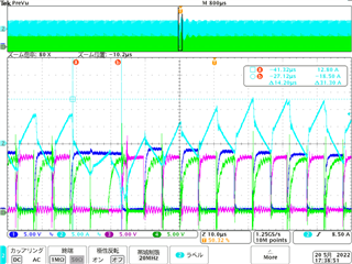
Please see waveform below;

-CH1 C_FET_Vgs

-CH2 transformer current

-CH3 D_FET_Vgs

-CH4 B_FET_Vgs

mode1

mode2

  • Hello,

    That can happen if the controller is trying to demand 0% duty cycle.  C and D will be shifted a 180 degrees to demand 0 duty cycle.

    The UCC28950 can also have irregular gate drive pulses if the design is using more than 90% duty cycle.  This issue was resolved in the UCC28951 and is described in an application note that you can find at the following link.  https://www.ti.com/lit/pdf/slua853

    If your design is going over 90% duty cycle I would suggest using the UCC28951.

    Regards,

  • Hi Mike 

    Thanks for your reply.

    I have already replaced it with UCC28951, but this bug still remains.

    Also, in the case of the problem that occurred in UCC28950, I think that short-time pulse inversion will occur, but this time it has not occurred.

    Therefore, this mode seems to be another malfunction.

    Please tell me the cause of this different mode.

    Below is the waveform confirmed that there is no short-term pulse inversion.

    -CH1 CS

    -CH2 transformer current

    -CH3 OUTD

    -CH4 OUTC

    Below is the waveform confirmed that the LL / EN terminal has not been pulled down.

    -CH1 LL/EN

    -CH2 transformer current

    -CH3 OUTD

    -CH4 OUTC

    Best regards

  • Hello,

    Why does your current sense signal have so much noise on it.  Where did you place your current sense transformer?

    It should be in front of the HBridge as the data sheet recommends.  Do you have a schematic that you can share?

    All of your waveforms seems quite noisy almost like you have a grounding problem.

    When I look at your CS signal before it seem to be gradually climbing and turns off after reaching the highest peak current. It is almost if at this point in time the controller is trying to demand 0% duty cycle.  You should study COMP, SS, and CS when this behavior occurs.  Please note COMP is noise sensitive and the data sheet gives recommendations on how to probe this pin. 

    If your LL/EN pin is SS/EN it looks like the design is not going into an OCP fault.  However, I just believe it is trying to demand 0 duty cycle.  Looking at the COMP pin will give you this information.

    I do think your CS signal is exceptionally noise.  That high frequency ring should not be on the CS signal. That also may be contributing to your issue.  If you remove that high frequency ring on the CS signal your issue may go away as well.

    Regards,


  • Hi Mike

    The current sense transformer is in front of the HBridge.
    I think the way of probing is bad. When I corrected the probing part, it became a clean waveform, so it seems that it has nothing to do with the problem.

    Is it a guess that the reason why the ON time is extended is that the Duty is narrowed down to 0% by OCP after operating at the maximum Duty?
    And is it because of the noise to the comp terminal that it works at maximum Duty in the first place?

    Is it possible to set Duty to 0% even though the voltage of the SS / EN pin has not dropped?
    I will check the voltage of the comp terminal, but could you explain the logic that this mode can occur?

    Best regards

  • Hello,

    You can demand 0% duty cycle without hitting OCP.  You need to study COMP and CS together to double check.  Also note that slope compensation will effect the duty cycle as well.

    Regards,

    Mike