This thread has been locked.

If you have a related question, please click the "Ask a related question" button in the top right corner. The newly created question will be automatically linked to this question.

UCC28251: Asymmetric half-bridge operation for off-line converters 400Vin to isolated 24Vout

Part Number: UCC28251
Other Parts Discussed in Thread: LM5036

Hello,

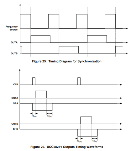
Is UCC28251 the best choice for asymmetrically driving a half-bridge (as opposed to 50% duty cycle on both top and bottom switches) for an off-line converter with 400Vin to isolated 24Vout?

If not, what would TI recommend for asymmetric half bridge operation?  Output power range is < 350W.

Regards,

Nitish

  • Hello,

    UCC28251 OUTA and OUTB are symmetric, this is good device for offline application with many advanced features. 

    If you want to use asymmetric control, maybe you can take one OUTPUT, then INVERT it to get complementary output for the other switch. It is complicated, but doable.

  • Hi Sean,

    Thank you for clarifying that UCC28251 is for symmetric driving.  Based on your response, is my understanding correct that TI doesn't have any controllers for asymmetric PWM control of half bridge?

    Regards,

    Nitish

  • Nitish,

    UCC28251 OUTA and OUTB are asynchronous D outputs not suited for the asymmetrical half-bridge (AHB). AHB requires a controller capable of producing D and 1-D outputs and TI has many controllers of this type. Any D, 1-D Application Specific PWM can be used from TI. these include the PWMs assigned to the active clamp topology and I parametrically searched them here for you.

    Why have you chosen the AHB topology?

    The AHB has some niche equipment applications but is not such a popular topology because it really works best when D is close to 50% (narrow VIN range) but the LLC converter also works best with narrow VIN and fixed VOUT and with the large number of LLC controllers in the industry, the AHB has sort of fallen by the wayside. Still, the AHB is a fixed frequency topology suitable for higher power compared to other 2-switch topologies and the LLC is a variable frequency 2-switch topology. There are some nuisances with the AHB converter topology you should be aware of. Please be sure you understand the trade-offs and limitations which are summarized below:

    Regards,

    Steve M

  • Hi Steve,

    Thank you for your response and providing link to your search result of asymmetric controllers with active clamp.  I note the disadvantages you have listed.

    Regarding high voltage stress on secondary rectifiers, how big of a concern would it be if the max voltage is limited to 62V?

    I need to understand the blocking capacitor transient response issue better.

    Regards,

    Nitish

  • Nitish,

    The asymmetrical voltage stress exists because of the wide range of D. In the graph I showed, you are only seeing a ~2:1 D variation and you can see how widely displaced the voltage distribution is between the two rectifier diodes. If you can find rectifiers that are safely rated to the worst case voltage/power stress than no worries. From a transient response point of view, the blocking cap in the AHB is similar to the resonant cap in a active clamp. Make it large and you reduce the ripple but take on the poor transient response because the cap voltage can't change instantaneously. Make it small and the transient response improves but the voltage ripple voltage increases. You need to find the sweet spot when you tune/test the hardware on the bench. 

    Steve

  • Hi Steve,

    Thank you again for your further explanations.  From reading your earlier message, am I understanding correctly that LLC topology is more suitable for a fixed output voltage?  For instance, if the output voltage varies between 16V~32V (for 24V nominal battery load) or 32V~64V  (for 48V nominal battery load), would LLC not be a suitable topology?

    You have mentioned certain differences between LLC and AHB....is there a comprehensive comparison between LLC and AHB topologies that you can point me to?

    Regards,

    Nitish

  • Nitish,

    Since AHB is not very much promoted at TI, I can't find and y direct comparison to LLC. I've done these types of comparisons and wrote some training materials you can find in the public domain here. Pay attention to slide 63 which I've clipped below from the slide deck.

    Regards,

    Steve

  • Hi Steve, thank you for your comments.  This is helpful.

    Regards, Nitish

  • Hi Steve / Sean,

    I have a few more questions about UCC28251 and LM5036 as well....LM5036 seems to be quite popular as there is plenty of discussion around it.

    1) Sean mentioned that UCC28251 is for symmetric driving and Steve mentioned that its outputs were asynchronous D outputs.

    1a) From the above I take it that both the upper and lower switches of the half-bridge at driven with the same duty cycle D....which would meant that D<0.5. Would you please point me to where in the datasheet the symmetric drive is mentioned?

    1b)  Kindly elaborate further your statement "UCC28251 OUTA and OUTB are asynchronous D outputs".  Since there is only one feedback pin whose voltage determines the duty cycle to drive the upper and lower MOSFETs with, I am really confused by "asynchronous outputs" mention in your statement.

    1c)  Would you please point me to where in the datasheet the "asynchronous outputs" feature is mentioned?

    2)  LM5036:  What does input voltage feed-forward mean?

    3)  Since Vin in LM5036 is limited to <100V, can I use it to drive a half-bridge connected to 400Vdc bus if I use isolated gate drivers and supply it with Vin generated from an auxiliary source?

    Your feedback would be appreciated.

    Regards,

    Nitish

  • Nitish,

    1) Sean mentioned that UCC28251 is for symmetric driving and Steve mentioned that its outputs were asynchronous D outputs.

    1a) From the above I take it that both the upper and lower switches of the half-bridge at driven with the same duty cycle D....which would meant that D<0.5. Would you please point me to where in the datasheet the symmetric drive is mentioned?

    [TI]: "symmetric" just means what you stated and is shown in Fig A, "Symmetrical Half-Bridge Diagrams" from the first diagram. I don't see the word "symmetric" mentioned in the UCC28251 data sheet but is implied by the waveforms below. You can see that OUTA and OUTB each respond to every alternate clock pulse and the combined result is symmetric:

    1b)  Kindly elaborate further your statement "UCC28251 OUTA and OUTB are asynchronous D outputs".  Since there is only one feedback pin whose voltage determines the duty cycle to drive the upper and lower MOSFETs with, I am really confused by "asynchronous outputs" mention in your statement.

    [TI]: Asynchronous (symmetric but 180 out of phase) means the same as "symmetric" from above. Sorry if that term caused confusion.

    1c)  Would you please point me to where in the datasheet the "asynchronous outputs" feature is mentioned?

    [TI]: Refer to 1b above

    2)  LM5036:  What does input voltage feed-forward mean?

    [TI]: In VMC, the control loop gain varies as a function of input voltage variation. VFF modulates and adjusts the RAMP signal proportional to input voltage variation to help improve regulation and transient response by overcoming this limitation of VMC.

    3)  Since Vin in LM5036 is limited to <100V, can I use it to drive a half-bridge connected to 400Vdc bus if I use isolated gate drivers and supply it with Vin generated from an auxiliary source?

    [TI]: LM5036 has internal integrated HV start-up and the pass transistor is limited to 100-V. You can start-up from higher line voltage but you need to bypass the internal start-up as described in the LM5036 data sheet, section 8.2.2.4.

    Regards,

    Steve M

  • Hi Steve,

    Thank you for answering my questions.

    I am trying to decide if symmetrically driven half bridge converters (such as with UCC28251 or LM5036) are suitable for wide output voltage range required in battery charging applications.  For instance, if the output voltage varies between 16V~32V (for 24V nominal battery load) or 32V~64V  (for 48V nominal battery load), with input voltage between 370V - 400V.  Output power < 350W.  I am assuming transformer isolation.

    Your further guidance will help me choose the correct controller.

    Regards,

    Nitish Agrawal

  • Nitesh,

    Within this E2E thread, I think we completed a thorough discussion comparing symmetrical vs asymmetrical converters. Whether either of these is best suited for your battery charger application depends on the voltage/current stress through the power stage for each of your defined corner cases and this is where we began this discussion. We concluded that LLC is not a good choice, AHB can use any of the TI, D, 1-D active clamp controllers I provided and any half-bridge controller can be used for a traditional hard-switched symmetrical half bridge. Can I propose we close this thread and you can open a new E2E thread with any additional questions you have? Thanks for connecting through E2E and exploring your design with TI products.

    Regards,

    Steve M

  • Hi Steve,

    Yes, thank you for your help.  I will start a new thread.

    Regards,

    Nitish

  • I am closing this thread. Thank you.