This thread has been locked.

If you have a related question, please click the "Ask a related question" button in the top right corner. The newly created question will be automatically linked to this question.

TPS65086100RSKT-burn the second OTP

Other Parts Discussed in Thread: BOOSTXL-TPS650861, IPG-UI

Thanks James,

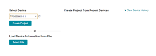
I want use the BOOSTXL-TPS650861 EVM to burn the second OTP in the PMIC in the TPS65086x Evaluation Module.

I will connect all the controls I2C, CTL4 and IRQB to 7V from BOOSTXL-TPS650861 EVM to TPS65086x Evaluation Module.

The motivation is to check my configuration on the TPS65086x Evaluation Module.

Are there any special requirements to do it?


Regards,

Moshe

  • Hi Moshe,

    As long as you have access to the correct source voltages for the EVM, I don't think there are many special requirements to consider. If you have a USB-A to USB-micro B connection cable, you should be able to connect the EVM to your computer and interface with the board through our IPG-UI software, rather than trying to pull the I2C from the BOOSTXL. You will need to use the TPS650861-1.1 option under "device selection" in IPG-UI so you can see the programming registers (0x38 address). From there, you just need to apply the appropriate VSYS and follow a few steps. I believe you should see both a green LED and a yellow LED to indicate that the EVM is connected to your computer and has sufficient power. Once that is confirmed:

    1) Apply 7V to CTL4 to gain access to the programming registers (0x38 address registers).

    2) (Recommended) Write bit 7 to a "1" in the OTP_CTRL1 register (R = 0x02). This allows you to stay in programming mode without applying 7V to CTL4 pin and is helpful to prevent accidental exit of programming mode. The CTL4 pin should not be held at 7V for more than a minute so if you plan to be changing registers for longer than a minute I would advise you write bit 7 and remove the 7V from CTL4. Alternatively, you can simply go to the "Device Controls" tab and click the "Test Mode" button in box 1 which will achieve the same result in about 800ms (make sure you have the 7V on CTL4 when you click the button).

    3) Select the OTP bank you want to program in box 2 under the "Device Controls" tab.

    4) Input desired settings to the programmable registers you want to change. You should have a programming script from the OTP Generator. Just go to the "Device Controls" tab in IPG-UI and select the correct OTP configuration in box 3. From there, you can click the "Write" button in box 4 and your OTP configuration will be loaded into memory. Use the "Check" button in box 5 to verify the registers.

    5) Apply 7V to the IRQB pin and write bit 1 to a "1" in the OTP_CTRL1 register (R = 0x02). After writing bit 1, you may remove the 7V on IRQB. Alternatively, you can go to the "Device Controls" tab and click the "Program OTP" button in box 6 (make sure you have the 7V on IRQB when you click the button).

    At this point you should have your EVM successfully loaded with the custom configuration. I will include some pictures below for clarity.

    IPG-UI Select Device option for user programming

    Programming registers address with OTP_CTRL1

    Device Controls tab in IPG-UI

    Regards,

    James

  • Thanks James,

    Why did you say "As long as you have access to the correct source voltages for the EVM"?

    I have a different voltage configuration from the EVM OTP 1 configuration.

    When i want to program second OTP in the PMIC, Do i need to force that CTL1-6 to '0' (Disable all outputs)?

    Regards,

    Moshe

  • Hi Moshe,

    I just meant that you need at least 5.6V on VSYS and a stable 7V for programming. It doesn't matter whether it comes from the BOOSTXL or a separate power supply. 

    I don't think it's absolutely required to have all the CTLx pins low for programming, but I would recommend you pull them low during the programming process, just to be safe. I wouldn't connect any power rail enables to CTL4 in your OTP settings since you will be using this pin for programming.

    Regards,

    James