This thread has been locked.

If you have a related question, please click the "Ask a related question" button in the top right corner. The newly created question will be automatically linked to this question.

LM3671MF-1.8EV: ugly power up

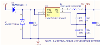
Part Number: LM3671MF-1.8EV

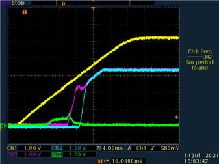
We are actually using the LM3671MF-3.3 device but it doesn't appear in the selection when creating this thread.  Upon application of 5V power (yellow trace), the 3.3V output of the LM3671 has a "stepped" startup that is causing our processor to improperly power on reset at times.  The load is relatively low mA but the output ripple is minimal so I believe it is running properly, it just starts up very janky.

  • As a note, farther down the power plane, we have a relatively large 11mF supercapacitor but this has a high internal impedance of 160 ohms and I couldn't understand how they would create this stepped startup curve.

  • Hi Dan,

    The LM3671 unfortunately has a stepped response in the output voltage during startup. Please see Figure 27 and 28 in the datasheet.

    The reason for this is that before startup, the internal reference of the converter is already at it typical value (0.5V) and only the current limit is changed in steps up to the typical current limit during the startup phase.

    Converters that have a smooth startup typically have the internal reference ramped up from 0 to the typical value during soft start. In case it is still possible to switch over to a new converter with a smooth startup for your project, I could recommend some other devices.

    On your current board can you try removing all the bulk caps and check how the startup looks like? Also do you have a ferrite bead between C6 and the bulk caps?

    Best regards,

    Varun

  • No ferrite but there is a TPS3620-33DGKR power switch.  Can you give me recommendations for similar converters that are widely available now?  I only need 300mA.

  • Hi Dan,

    11mF is too high an output capacitance for any of our devices to directly drive. This can cause the device to be unstable or sometimes even go to current limit. Keeping a ferrite bead / inductor between the output cap of the buck converter and the bulk output cap can help reduce it's influence on the loop of the buck converter. Can the 11mF be reduced or even removed?

    TPS62A01 and TPS62824 are 1A converters that support < 50uF output capacitance. TPS628501 is also 1A converter that can support 200uF of output capacitance. All of them have a smooth startup ramp.

    Best regards,

    Varun

  • Thanks Varun,

    Can you recommend a small ferrite spec that would help.  The capacitors also have a series resistor to limit the charge current...would using that reduce the influence on the loop of the converter?  What current limit would make sense for the TPS3620?

    We previously had a linear in this circuit.  Would it make sense to revert to that type of supply as we can't remove the large capacitors?

  • Hi Dan,

    Please allow me to jump in since Varun is currently out of office.

    Thanks a lot for your question.

    We will look into it and come back to you in a couple of days.

    Thanks,

    Stefano

  • Hi Dan,

    Sincere apologies for the delayed response. Some of our team mates are still on vacation.

    - Generally, we do not recommend any particular ferrite bead. Because this depends on the system design and the range of frequencies that needs to be attenuated. What you must look for is the 'impedance vs. load current' curves and ensure that the ferrite bead can withstand the system load current without saturating and losing their impedance within the desired frequency range.

    - From the datasheet, the FET current limit is between 830-1150mA.

    -

    We previously had a linear in this circuit.  Would it make sense to revert to that type of supply as we can't remove the large capacitors?

    Do you mean, using LDO instead of Buck?

    Thanks,

    Febin

  • Yes, 300mA LDO

  • Also, if I contain the charge current of the capacitors to 1A with a series resistor, does that negate the use of the ferrite?

  • Hi Dan,

    - LDO could be an alternative.

    Also, if I contain the charge current of the capacitors to 1A with a series resistor, does that negate the use of the ferrite?

    How about the total output cap?

    Regards,

    Febin