This thread applies to the TPS65086x devices, and specifically to the TPS650861 and TPS6508641 devices with regard to BUCK1.
The TPS650861 PMIC has three Buck controllers: BUCK1, BUCK2, and BUCK6. Each controller has an external feedback input pin (FBVOUTx) that should be connected to the positive terminal of the output capacitors for regulation. Alternatively, the feedback line can be connected close to the output load to ensure that the voltage seen by the target device is at the desired level.
Most of the time, an added RC filter is the only consideration that should be made for each of the buck controller FBVOUTx lines. The feedback network needs to receive the same voltage from the buck output that is programmed in the OTP settings. Any external components that significantly alter the buck output voltage on its way to the FBVOUTx pins will disrupt the output regulation.
BUCK1 has the option to function in a fixed 5V output mode. When the TPS650861 is programmed for the BUCK1 fixed 5V output (the EXT FB option in the OTP Generator), the FBVOUT1 line will require an additional resistor divider network to ensure proper voltage regulation. BUCK1 is the only controller where a resistor divider should be used on the feedback line, since it is the only power rail with the fixed 5V output capability. Note that the TPS6508641 PMIC has BUCK1 programmed to the fixed 5V output by default.
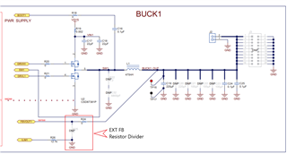
With the fixed 5V setting enabled, BUCK1 will only output 0.4V if no resistor divider is in place. The FBVOUT1 pin will be using this 0.4V as a reference for regulation at all times. In order to get BUCK1 to output 5V, a resistor divider network must be used to drop the desired 5V output to the 0.4V target. Below is a picture of the BUCK1 schematic from the TPS65086x EVM User's Guide. In order for BUCK1 to output the proper 5V, one could replace R24 with a 294 kΩ resistor and populate R25 with a 25.5kΩ resistor. This would provide the necessary voltage drop for the FBVOUT1 pin to see 0.4V from the desired 5V output. With this network in place, BUCK1 should automatically rise to 5V after the rail is enabled (the exact resistor values may vary depending your design needs).
If BUCK1 is to be changed from this fixed 5V output, the resistor divider network should be removed to support normal regulation conditions.
BUCK1 schematic from the TPS65086x EVM User's Guide