This thread has been locked.

If you have a related question, please click the "Ask a related question" button in the top right corner. The newly created question will be automatically linked to this question.

LP8864-Q1: LP8864 Failure Issue

Part Number: LP8864-Q1

Hi,

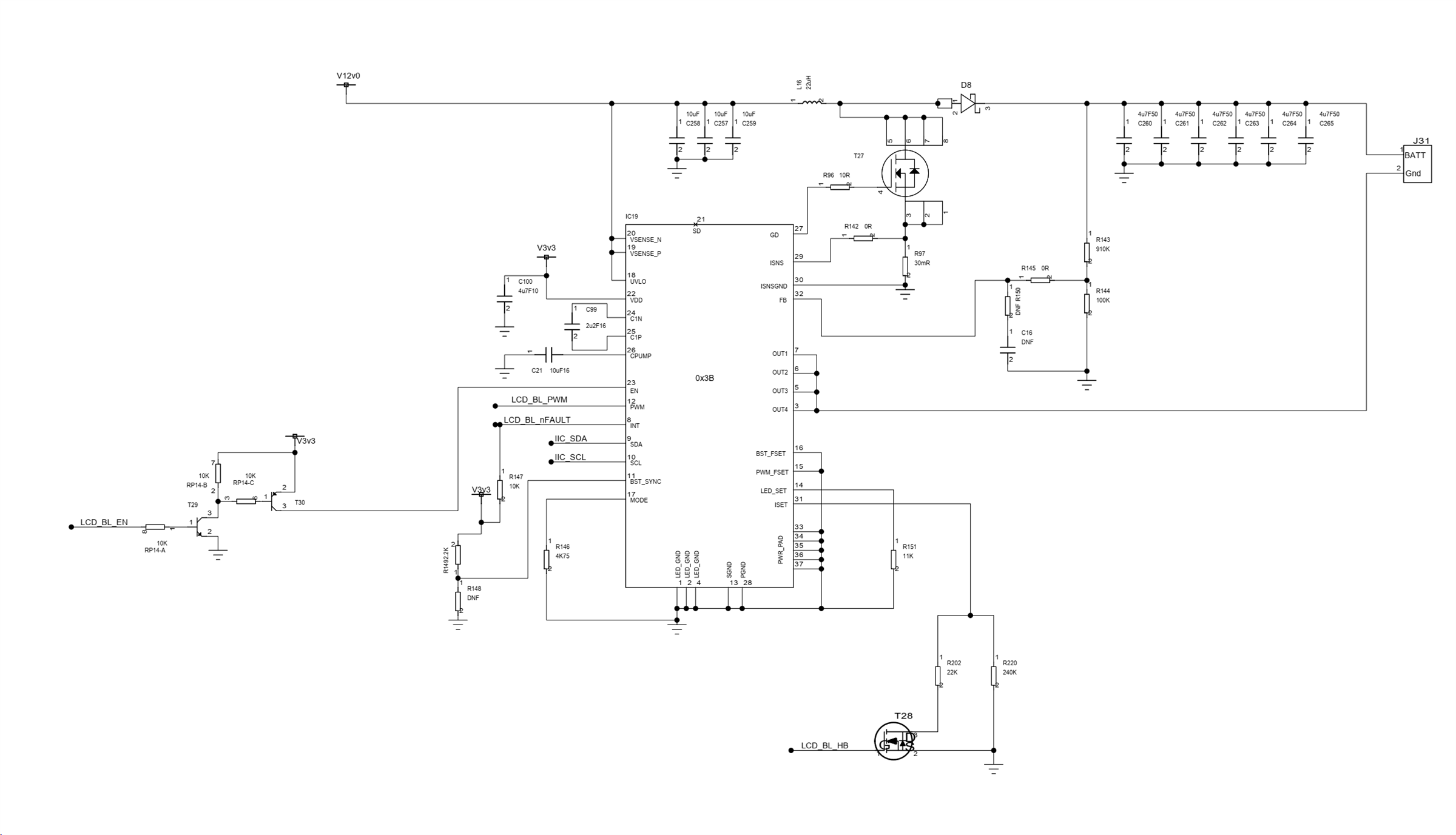
We are using the LP8864 as shown in the schematic below, but are seeing failures when the backlight brightness is reduced to a low value via PWM.

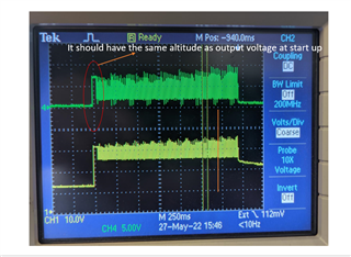
When a certain threshold is reached the LP8864 goes into fault mode and the only way to recover it is by bringing the brightness (pwm up) and disabling & reenabling the device.

This error is not being seen by all our units, even thou the design and components are exactly the same.

I'll be greatful of any comments.

Thanks

  • Hi, James, 

    Could you read out all register data? 

    Also, With INT pin trigger, to capture below waveforms with oscilloscope; showing each item in a plot.
    (1). Vin, Vsen_N, SD
    (2). Cpump, VLDO, VDD
    (3). Switching node, GD, ISNS, Vout
    (4), Vout, LEDx, FB

  • Hi,

    Many thanks for your message;

    Incase it help - on the boards that work, VOUT remains constant while the PWM is in a low state, as opposed to falling on the faulty boards that fail at low brightnesses.

    Please see the following results:

    Register data (I think only the first two lines of each data set are applicable):

    Working (100% Brightness):
         0  1  2  3  4  5  6  7  8  9  a  b  c  d  e  f    0123456789abcdef
    00: 00 00 ff 0f a3 08 00 01 aa 2a 28 a0 aa 00 00 00    ...???.??*(??...
    10: 00 00 00 00 10 00 14 ff 00 00 ff 0f 25 06 1b 0c    ....?.?....?%???
    20: 00 00 00 00 00 00 00 00 00 00 00 00 00 00 00 00    ................
    30: 00 00 00 00 00 00 00 00 00 80 00 00 00 00 00 00    .........?......
    40: 00 00 a1 00 00 00 00 00 ff 00 00 00 00 40 00 00    ..?..........@..
    50: 00 00 00 00 00 00 00 00 00 00 00 00 00 00 00 00    ................
    60: b3 8f b1 b0 51 8f 10 b0 d0 f0 f0 92 a8 9e b2 ef    ????Q???????????
    70: 7a fe ac ec 00 42 49 01 11 04 00 ff aa 55 aa 5f    z???.BI???..?U?_
    80: 00 00 00 00 00 00 00 00 00 00 00 00 00 00 00 00    ................
    90: 00 00 00 00 00 00 00 00 00 00 00 00 00 00 00 00    ................
    a0: 00 00 00 00 00 00 00 00 00 00 00 00 00 00 00 00    ................
    b0: 00 00 00 00 00 00 00 00 00 00 00 00 00 00 00 00    ................
    c0: 00 00 00 00 00 00 00 00 00 00 00 00 00 00 00 00    ................
    d0: 00 00 00 00 00 00 00 00 00 00 00 00 00 00 00 00    ................
    e0: 00 00 00 00 00 00 00 00 00 00 00 00 00 00 00 00    ................
    f0: 00 00 00 00 00 00 00 00 00 00 00 00 00 00 00 00    ................

    Working (50% Brightness):
         0  1  2  3  4  5  6  7  8  9  a  b  c  d  e  f    0123456789abcdef
    00: 00 00 ff 0f a3 08 00 01 aa 2a 28 a0 aa 00 00 00    ...???.??*(??...
    10: 00 00 00 00 10 00 07 87 00 00 ff 0f 31 06 1b 0c    ....?.??...?1???
    20: 00 00 00 00 00 00 00 00 00 00 00 00 00 00 00 00    ................
    30: 00 00 00 00 00 00 00 00 00 80 00 00 00 00 00 00    .........?......
    40: 00 00 a1 00 00 00 00 00 ff 00 00 00 00 40 00 00    ..?..........@..
    50: 00 00 00 00 00 00 00 00 00 00 00 00 00 00 00 00    ................
    60: b3 8f b1 b0 51 8f 10 b0 d0 f0 f0 92 a8 9e b2 ef    ????Q???????????
    70: 7a fe ac ec 00 42 49 01 11 04 00 ff aa 55 aa 5f    z???.BI???..?U?_
    80: 00 00 00 00 00 00 00 00 00 00 00 00 00 00 00 00    ................
    90: 00 00 00 00 00 00 00 00 00 00 00 00 00 00 00 00    ................
    a0: 00 00 00 00 00 00 00 00 00 00 00 00 00 00 00 00    ................
    b0: 00 00 00 00 00 00 00 00 00 00 00 00 00 00 00 00    ................
    c0: 00 00 00 00 00 00 00 00 00 00 00 00 00 00 00 00    ................
    d0: 00 00 00 00 00 00 00 00 00 00 00 00 00 00 00 00    ................
    e0: 00 00 00 00 00 00 00 00 00 00 00 00 00 00 00 00    ................
    f0: 00 00 00 00 00 00 00 00 00 00 00 00 00 00 00 00    ................

    Failed (~10% Brightness):

         0  1  2  3  4  5  6  7  8  9  a  b  c  d  e  f    0123456789abcdef
    00: 00 00 ff 0f a3 08 00 01 aa 2a 28 a0 aa 00 00 00    ...???.??*(??...
    10: 00 00 4f 04 13 00 01 27 00 00 ff 0f ff 07 1b 0c    ..O??.?'...?.???
    20: 00 00 00 00 00 00 00 00 00 00 00 00 00 00 00 00    ................
    30: 00 00 00 00 00 00 00 00 00 80 00 00 00 00 00 00    .........?......
    40: 00 00 a1 00 00 00 00 00 ff 00 00 00 00 40 00 00    ..?..........@..
    50: 00 00 00 00 00 00 00 00 00 00 00 00 00 00 00 00    ................
    60: b3 8f b1 b0 51 8f 10 b0 d0 f0 f0 92 a8 9e b2 ef    ????Q???????????
    70: 7a fe ac ec 00 42 49 01 11 04 00 ff aa 55 aa 5f    z???.BI???..?U?_
    80: 00 00 00 00 00 00 00 00 00 00 00 00 00 00 00 00    ................
    90: 00 00 00 00 00 00 00 00 00 00 00 00 00 00 00 00    ................
    a0: 00 00 00 00 00 00 00 00 00 00 00 00 00 00 00 00    ................
    b0: 00 00 00 00 00 00 00 00 00 00 00 00 00 00 00 00    ................
    c0: 00 00 00 00 00 00 00 00 00 00 00 00 00 00 00 00    ................
    d0: 00 00 00 00 00 00 00 00 00 00 00 00 00 00 00 00    ................
    e0: 00 00 00 00 00 00 00 00 00 00 00 00 00 00 00 00    ................
    f0: 00 00 00 00 00 00 00 00 00 00 00 00 00 00 00 00    ................

    The plot below shows the following:

    Blue - Vin

    Purple - Vout

    Yellow - INT

    VSEN is not used - connected to VIN, SD is not used, and is open circuit.

    The plot below shows:

    Blue - CPUMP

    Purple - VDD

    Yellow - INT

    The plot below shows:

    Blue - Switch Node

    Green - ISNS

    Purple -GD

    Yellow - VOUT

    The plot below shows:

    Blue - FB

    Green - LeDx

    Yellow - Vout

    The plot below shows the device from enable to failure. As seen in the plot below the output volatge increases, Ledx voltage icreases which causes the device to fail as it thinks the LED chain have gone open circuit.

    Thanks,

    James

  • James, 

    From the register data, it seems all ports run into open LED detected. Also, 1Ch register shows that output voltage reached maximum output voltage up to 47V. 

    The dimming duty cycle shown in the waveform is far below 10%, right? I also could not detect high output voltage from the tested waveform. 

    Can you help try adding more output capacitance, like 1 33uF Al cap? The capacitance in current design is not large enough for stable, especially when the DC-bias effect is considered.  

    Please also help check load connection. What is load spec? Generally, LEDx voltage should be pulled up to Vboost at beginning if LED string is connected with 0 current. It starts to drop down to headroom voltage after dimming starts.  

    Regards, 

    XG

  • Hi,

    The dimming ratio is about 15%, we have also set the maximum voltage with the feedback resistors to about 33v, not 47v

    I have just added another 6 off 4.7uF 50v ceramic caps to the output, taking the capacitance to just under 60uF

    I have also just put a 1R current shunt at the bottom of the LEDs, and with a scope across this - there looks to be a current sink of about 100mA into the LED current sink pins when the PWM is in the off state - surly this can't be correct?

    LED current when the PWM is in the on state is about 600mA

    Also note the circuit is connected with all LED current sinks in parallel to get a bigger LED current.

    Many thanks for your support so far.

  • Hi, James, 

    If there is test condition along with the waveform, it would be helpful for me to better understand the issue. 

    It seems you are choosing hybrid mode for dimming. With 15% duty cycle, you'll see constant 90mA(600x15%) sink current.  That's the reason you still see constant 90mA current when PWM is off. 

    1. Does the issue also happens when duty cycle is 15%? (As 12.5% is the threshold for current mode changing to PWM mode) Can you gradually reduce duty cycle and record the value when the issue starts to happen? 

    2. Does the issue also happen when maximum voltage is set to 47v? If so, please help share the waveform and let me know setting(schematic, PWM, etc.), If still happens, please check if additional output capacitance helps.  

    I guess one possible reason is that with reduced dimming current, output voltage is charged up to higher voltage by energy stored in the inductor and triggered Open LED fault. If so, adding more capacitance and changing max output voltage to higher voltage should be helpful.  

    Regards, 

    XG.