This thread has been locked.

If you have a related question, please click the "Ask a related question" button in the top right corner. The newly created question will be automatically linked to this question.

TPS62866: I2C address corresponding to an invalid Vset resistor

Part Number: TPS62866

Hi,

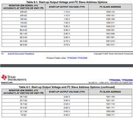
I am using the part switching regulator TPS62866. The Vset resistor values and the corresponding I2C addresses are specified in the table for setting the output voltage.

If a resistor value outside those mentioned in the table is used, say 1k(which is lower than the min value of 10k mentioned in the table), then is there a default I2C address that the controller responds to?

Thanks

Shruti 

  • Hello Shruti,

    To understand more how the resistor-to-digital works, I recommend you read the following Paper

    The resistor-to-digital circuitry is connected to an internal ADC. Then, if you are using a resistor value below the min, the min read out will occur meaning 0.4V.

    You can also link the VSET/VID pin to GND and after startup the device will startup at 0.4V.

    Let me know.

    Thanks a lot!


    Regards,
    Dorian 

  • Hi Dorian,

    As per above reply, I would expect the start up voltage to be 0.4V and address to be 0x47 if I connect the Vset pin to GND.

    I ran a few tests on the eval board and here are my observations:

    • Connecting the Vset/Vid pin directly to ground using a jumper on the EVM board results in the startup voltage and I2C address - 0.9V, 0x46
    • At Rset = 249Ohm(random low value), the startup voltage is 0.9V and the I2C address is 0x46

    This is the same address, as the address for Rvset=249kohm(1.15V Vset). However, the default voltage is 0.9V.

    So whether I use a 249kohm resistor to set the address to 0x46 or have some invalid low value resistor, the address gets set to 0x46. This is not in line with what we would expect, right?

  • Hello Shruti,

    Let me come back to you tomorrow on that topic.

    Thanks a lot!

    Regards,
    Dorian

  • Hello Shruti,

    Do you have the Jumper JP1 connecting (VID/PG & High) ? Can you make sure to connect VID/PG to GND using JP1 ?

    If so, the ADC will see a logic High and interpret this as a being the highest readout - 1.15V.

    Also, the device will refer to the Vout register 2 because the VID is set a high logic and the default value on Vout register 2 is 0.9V.

    Let me know.

    Thanks a lot!

    Regards,

    Dorian 

  • Hi Dorian,

    Yes, the VID/PG  pin is connected to GND using JP1. It was never connected to High. 

    With this connection, I changed the resistor R1 with various values and below are my observations about default voltage and I2C address.

    • 0 ohm- default voltage 0.9V, address 0x46
    • 249 ohm- 0.9V, 0x46
    • 249kohm - 1.15V, 0x46

    The eval board comes with 86.6kohm with which the default voltage is 0.9V and address is 0x41. I observed the same.

    What concerns me is that the module responds to 0x46 address and comes up with 0.9V default when a smaller resistor out of range is used(say 0ohm). Is this expected behaviour?

    Regards

    Shruti  

  • Hello Shruti,

    What is exactly the purpose of your measurement here ? E96 resistors (with 1% accuracy) are quite common to find.

    The defined and validated results are listed in the datasheet as such, the start-up output voltage and device I2C slave address are set by an external resistor connected to the VSET/VID. 

    This is table is the expected behavior.

    Let me know if you have any questions.

    Thanks a lot!

    Regards,
    Dorian

  • Hi Dorian,

    Thanks for your response. My purpose was to understand the behaviour of the device when resistor is out of range. If there is an understanding about the behaviour in that case.

    However, you are right to say that if the resistor value is correct then the behaviour of the device is as per the table. I will close this issue.

    Thanks for your time.

    Regards

    Shruti