This thread has been locked.

If you have a related question, please click the "Ask a related question" button in the top right corner. The newly created question will be automatically linked to this question.

LM5039EVAL: LM5039 hiccup mode discussion

Part Number: LM5039EVAL
Other Parts Discussed in Thread: LM5039

Hi Team

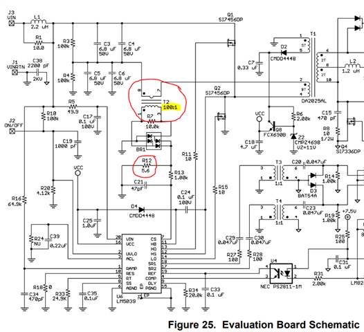
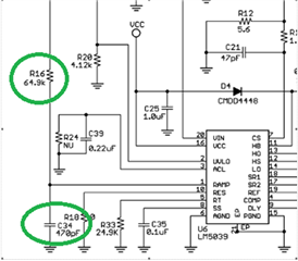
 LM5039 EVM file (attached) p4
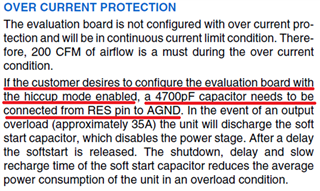
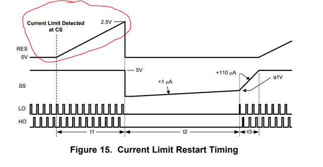
The content shows that to execute hiccup mode, the RES pin should be changed to 4700pF
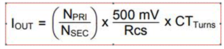
May I know how this value came from?!  Do we have calculation formula that could approve it? Thank you....

snva423c.pdf

  • Kygo,

    If a constant OC event is sensed and a capacitor is connected between RES and AGND, the behavior will be hiccup mode. Once the OC event is detected at CS a 22-μA current source charges the capacitor at RES until 2.5 V is reached. The value of the capacitor will determine how long the converter remains operating in OCP until 2.5V is reached, pulse packet terminates, SS begins and the next packet of pulses resumes. The formula for this is straight forward as charging a capacitor with a constant current source. I=C*dV/dt or C=I*dt/dV, where I=22 μA, dt is the desired time to remain switching and dV=2.5V.

    A small capacitor value will make the pulse packet duration smaller relative to the SS time and dissipate less average power while the converter remains in OCP. A larger capacitor value allows more time for the fault to be removed and the converter to recover but also means more average power dissipation if the OC fault is not removed. The image below from the LM5039 data sheet captures the RES behavior during OCP and the circled area represent the dV/dt1 where t1 is set by the capacitor value. From the app note you attached, t1~534 μs for C=4700 pF.

    Regards,

    Steve M

  • Hi Steven 

    Thanks for your support!

    More question,

    1.The formula in the Current Limit description of the LM503​​​9 specification (p12) is as follows


    NPRI and NSEC should refer to the transformer turns ratio! !
    >>>May I  know how RCS and CTTURNS are defined? ! Thanks! ! !

    2.Contents of Average Current Limit of DATASHEET (p22)
    If customer want to execute hiccup mode under Average Current Limit, please help to confirm two things?

    ・Are there any other restrictions on ACL pin capacitors?!
    ・And the capacitance value of RES must bigger than the capacitance value of ACL?! right ?Thank you...

  • Kygo,

    see [TI] responses below:

    1.The formula in the Current Limit description of the LM503​​​9 specification (p12) is as follows


    NPRI and NSEC should refer to the transformer turns ratio! !
    May I  know how RCS and CTTURNS are defined?

    [TI]: RCS is the current sense resistor shown as R12 below. CT_Turns is the CS Xfmr turns ration shown as 100:1, highlighted and circled T2 below.

    2.Contents of Average Current Limit of DATASHEET (p22)
    If customer want to execute hiccup mode under Average Current Limit, please help to confirm two things?

    ・Are there any other restrictions on ACL pin capacitors?!

    [TI]: Use SMD ceramic, X7R or better, rated for temp and tol according to the application you are considering.


    ・And the capacitance value of RES must bigger than the capacitance value of ACL?! right 

    [TI]: Correct

    Regards,

    Steve M

  • Hi Steven 

    Thanks for your support!

    More question,

    1.From LM503​​​9-EVM Calculation formula


    The Current Limit result is 

    >>>Now customer setting the Current Limit =35.7A, but no action is executed?! May I ask which pins or functions need to be checked to debug?!


    2.Customer currently uses the current sense resistor architecture as shown in the figure below , does the RCS in the formula above refer to the R1 in the figure below?!
    And how is the define of the CTturns?


    3.Feed-Forward Ramp and Volt • Second Clamp
    According to spec(p15) the following formula is the specification 2.2V
    So in normal operation the peak voltage of the RAMP pin triangle waveform will be 2.2V?!


    4.How are RFF(64.9K) and CFF(470pF) calculated? Can you provide the calculation formula? THX

  • Kygo,

    Monitor the CS pin during full load operation. If the average hits 500mV or peak hits 600mV you should see the output foldback or terminate accordingly. Make sure you have the CS filter adjusted correctly. Too much RC fliter on CS can reduce the peak and not give the expected result relatice to the signal appearing across the CS resistor.

    Your assumption is correct on the RAMP amplitude and is also given in the data sheet parameters as:

    RFF and CFF are on page 15 of the ds. Choose 470pF and calculate Rff according to your desired Ton (+10%, max duty clamp):

    It seems the questions you are asking are clearly answered directly from the data sheet. I hope you are reading the data sheet so you can best support your customer - is the data sheet information making sense?

    Reagards,

    Steve M