This thread has been locked.

If you have a related question, please click the "Ask a related question" button in the top right corner. The newly created question will be automatically linked to this question.

TPS63020: Need explanation of the buck-boost behavior TPS63020

Part Number: TPS63020

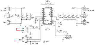
I am using buck-boost TPS63020DSJT on two PCBs made at different time intervals (implying that the buck-boosts are probably from different batches). Although the two pcbs have the same BOM and identical layout, I noticed that the buck-boost reacts differently.

The attachment file highlight the behavior obtained in the two PCBs.

The input/output capacitors as well as the related Buck-Boost component have been verified measured and shown no difference!

Even more, if I sawp the Buck-boost from PCB to another, I found that the behavior stick to its buck-boost IC (No influence from PCB or components could be highlighted)!


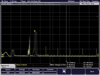
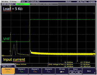
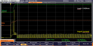
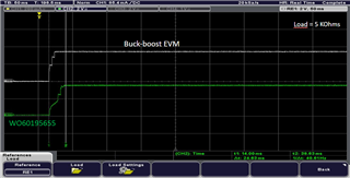
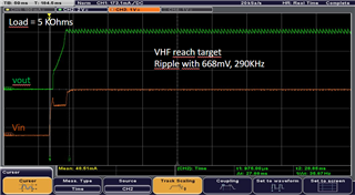
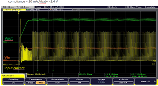
   - Behavior of TPS63020DSJT used in PCB1 :

Vout with lower ripple 

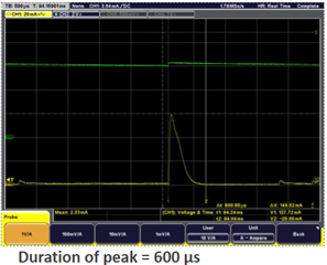
lower current inrush peak with a higher repetitive frequency

                                                                   VS


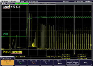
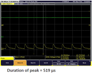
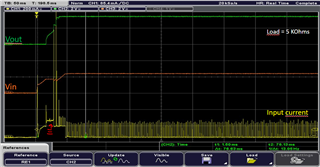
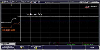
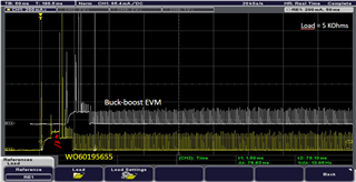
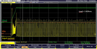
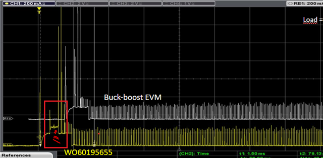
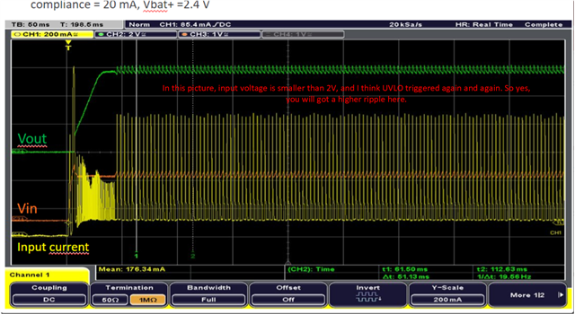
 - Behavior of TPS63020DSJT used in PCB2 :

Vout with Higher ripple 

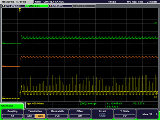
Higher current inrush peak with a lower repetitive frequency


Could you please help me to understand this behavior?

Have you encountered this type of issue before?

What investigation should I do to solve this issue?


Thank you in advance for your support.


Best regards.

HafedhSchematic_measurments.pdf

  • Hi   Hafedh,

    during PSM working, the pulses is decided by the comparator internal, and there will  be some difference, such as delay time and threshold between different devices.

    i think that is why you got the different performance.

    Regards

    Tao

  • Dear Tao,

    Thank you for your prompt reply.

    I can understand that some difference could be take into account between devices.

    But in my case, this difference is huge.

    The first TPS63020 shown : 

    Peak current value arround 10 mA each 4ms

    The second TPS63020 shown : 

    Peak current value arround 50mA each 13ms


    Even more, when I add a load of 5 KOhms, the difference increase and the output voltage shown higher dropout compared to device 1 (see curves below)

    Device 1

    Device 2

    The duration of the peak current of the both device TPS63020 are almost the same but the amplitude are different.

    Device 1

    Device 2

    Could you please clarify more about this strange behavior?

    Thank you in advance for your support.

    Best regards.

    Hafedh

  • Hi  Hafedh,

    thanks for your detailed description.

    that is really strange and i think these should not be caused by device. could you help to do a bench test with same board but different device?

    or you did it already and the picture attached are got with a same board?

    Regards

    Tao

  • Hi Tao,

    Yes I did the test on the same board.

    The behavior of the old Lot of TPS63020 is differents compared to the new Lot!

    Furthermore, if I sawp the Buck-boost from test bench to another, I found that the behavior stick to its buck-boost IC (No influence from PCB or components could be highlighted)!

  • Hi   Hafedh,

    ok, thanks for your detailed work.

    could you help to capture the current of inductor with these different device? also, if you can share your layout, it is better.

    Regards

    Tao

  • Hi Tao,

    Sorry for the delay.

    Actually, I bought a TPS63020EVM to use it as unique bench test (cf.schematic).


    Here below the measurements of the TPS63020EVM. (Vin = 2.4V; Current limit drive by power supply limited to 20 mA= compliance; Load = 5 KOhms)

    Then, I removed the original buck-boost and I replaced it by Buck-boost coming from last batch.

    Here below measurements results (Same settings : Vin=2.4 V; compliance= 20mA; Load = 5KOhms)

    You can observe that something wrong with these buck-boost! which I do not have any explanation Disappointed

    Furthermore, When I reduced the compliance to 10 mA. The buck-boost came from the last batch fails to start (see measurements below).

    However, the buck-boost of the evaluation board managed to start with a slightly longer start-up time compared to the compliance settings at 20 mA.

    On the other hand, if we consider that the compliance settings plays an important role. So, why when I increase the compliance to 100 mA, the output voltage reaches the target (cf. measurements below) but with higher ripple about 660mV?


    We have not yet found the solution for this issue.

    Your prompt feedback is very appreciated.

    Thank you in advance for your support.

    Br

    Hafedh

  • Hi   Hafedh,

    that is ok, you really did a great and detailed work.

    i am sorry i did not get your point about the wrong about the first part of attached picture. do you mean the part surrounded by a red frame below?

    actually, i think everything is ok here.Joy

    but yes, it seems abnormal that you got a higher ripple with 100mA current limit, i think i need some bench test to confirm. seems have something to do with slope of VIn during start-up.

    with 10mA current limit, you can see UVLO triggered again and again.

    Regards

    Tao

  • Hi  Hafedh,

    hope you are doing well,

    i am sorry i will not back to office till the beginning of july for some personal reason, so i am not able to do bench test till then.

    are you still waiting my bench test results?

    Regards

    Tao

  • Hi Tao,

    Sorry for the delay. I had problems logging into my TI account

    I didn't find yet the root cause.

    Today, I am afraid that almost all Buck-boost from the bashes purchased has this issue.

    Has this ever happened to you in the past?

  • Hi Hafedh,

    i am afraid not. no such issues happened before. 

    mostly, i think it is not a ture issue but i need some bench to confirm.

    Regards

    Tao

  • Hi Tao,

    Did you perform a test bench to confirm measurements?

    From my side, I did efficiency measurements (here below).

    The results shows efficiency below 70% in power save mode !


  • Hi   Hafedh,

    i will back to office and do the bench test next week.

    Vout is 6.3V in your test? i think it is out of spec, could you double check it?

    Regards

    Tao

  • Hello Tao,

    my bad, I will redo the measurement by adjusting the output voltage to 5V.

    Thank you

    BR

    Hafedh

  • Hi   Hafedh,

    that is ok, sorry for my delay.

    just a reconfirm,seems we have only one question that with 100mA current limit of source, the output ripple is higher than normal one, right?

    Regards

    Tao

  • Hi Tao,

    Yes, with 100 mA current limit of source, I obtain ripple higher than normal, about 668mV!

    If I use 20mA current limit of source, The buck-boost stay OFF (here below).


    I didn't see this behavior with old batches of TPS63020.

    BR

    Hafedh 

  • Hi  Hafedh,

    i did some bench tests with a TPS63020EVM, but unfortunatly, everything goes well and i can not see the behivor you got.

    like the  picture below.

    then i review our conversation, and i found some problems below.

    • input is really low and i am afraid UVLO triggered in your test. input pulled down once device start switching, it is depend on the behivor of DC source itself. with same compliance, there behivor can be very different.
    • output volt is out of spec and we can not ensure device will work as expected

    Regards

    Tao