This thread has been locked.

If you have a related question, please click the "Ask a related question" button in the top right corner. The newly created question will be automatically linked to this question.

TPS61094EVM-066: Defective Evaluation Module (2nd unit) or Mistake Trying to Make It Work

Part Number: TPS61094EVM-066
Other Parts Discussed in Thread: TPS61094

This inquiry is regarding a suspected-faulty, Texas Instruments (TI) TPS61094EVM-066 evaluation module OR a mistake trying to test this evaluation module - a distinct possibility.  This evaluation module enables customers to experiment with different modes of operation of the TI, TPS61094. For our application we intend to use the TPS61094 in the “automatic buck-boost mode”.

We are using a Beagle Bone Black (based on another TI product) single board computer that needs to fully shut down its operating system and MySQL before the power goes away … or bad stuff happens to our database. With a super-capacitor and the specified operation of the TPS61094, we should be able to tolerate random power outages that frequently occur at our industrial clients.  Once the AC power goes away, we only need to keep the Beagle Bone Black (BBB) board running for 12 seconds at 5 volts -  until the various software systems (especially MySQL) are shutdown gracefully. After the 12 seconds, we are happy to stay quiet without power until the AC power interruption is fixed and 5-volts returns to our BBB.

Our requirements are very straightforward and within the specifications of the TPS 61094. And, the Evaluation Module will be an easy way for us to test this chip in our application. If we could make this Evaluation Module function as specified, we would simply connect our normal 5-volt power supply to the input of the TPS61094 Evaluation Module and the connect the output of this module to the power supply input of our BBB using one of our prototype boards.  This should have been a trivially simple test --- but it did not turn-out that way.

Although we are very experienced individuals (BS-EE, MS-EE, PhD-EE from big 10 universities) with a combined total of 50 years of experience, we can still make "stupid/silly" mistakes. Advanced degrees and years of industrial experience are no guarantee against mistakes.

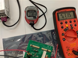
All of our tests resulted in the same electrical response ----  The output voltage precisely tracked the input voltage. That is, the output and input voltage were identical in value. There was no measurable charge (0-volts) on the super-capacitor.  The TPS61094 IC may be DoA/broken/damaged but it seems to be operating in a “forced bypass” mode.

There was no measurable 1MHz pulse width modulation frequency at pin #5 (SW)

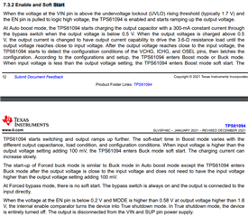
The “boost” mode failed to operate with the input voltage was decreased below the target output voltage and the “buck” mode failed to operate when the input voltage was raised above the target voltage.

The voltages measured at each of the 12 pins on this device seemed to be reasonable for each different pin. Except pin #5 and #6. There was no 1MHz signal and there was no voltage on the super-capacitor (as noted above).

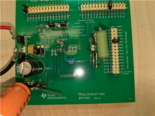
For our tests, we set the on-board jumpers as follows:

J1 and J5 were used as the  Vin+ and Power Supply Ground

 J7 (+) and J10(-) were connected to our 35 Farad super-capacitor while respecting the polarity of the super-capacitor.

J11 (Mode) and J12 (EN) were both set to “High” connecting pin1 to pin 2 with the provided jumper block.

J11 and J12 set the chip’s operational mode to automatically Buck or Boost as needed; this is the mode we care about for our application.

J3 (Vout+) and J6 (Vout -) were used to connect the output voltage to a resistive load for initial tests including (30 0hms, 100 ohms, 1M ohm)

JP1 and JP2 were set to short pins 2 and 3. These settings were required to use this device in the super-capacitor mode. This JP1 & JP2 configuration connected our 35 Farad super-capacitor to Pin #6 of the TPS61094 IC and to one side of the L1, 2.2 uH inductor.

JP3 was connected to R6 (13.0 k ohm) so that pin #12 (Vchg) of the TPS61094 would be connected to ground through 13.0 k-ohms.  This set  the supercapacitor charging voltage limit to 2.7 volts.

JP4 connected R26 (75.0 k-ohms) to pin #11 (Ichg)of the TPS61094 to set the charging current limit to 250 mA.

JP5 connected R45 (274 k-ohms) to pin #1 (OSEL) of the TPS61094 to set the output voltage to 5.2 volts.

For these tests, the load was set to 30 ohms, 100 ohms and 1M ohms. All resistors were separately measured to confirm the resistance values

For these tests, our super-capacitor was a 35 F device rated at 3.0 volts for a fully charged unit without damaging the capacitor. This capacitor was independently tested and charged to 1.5 Volts without issues.

The TPS61094 appears to be “stuck” in a forced bypass mode, even though both EN  and MODE lines are set high with on-board jumpers. In addition, I measured the voltage signals going into pin#2 (MODE) and pin #3 (EN). Both values tracked the Vin supply voltage. The output voltage also precisely tracked the input voltage  as described for the “forced bypass mode”. During these tests, the Vin supply voltage was varied from 2.9 volts to 5.1 volts.
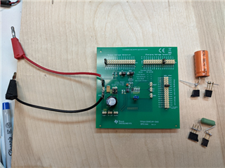
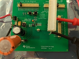
Images Below:

Photos of our copy of the TI  TPS61094EVM-066 Evaluation Module with test components – 35 Farad 3.0 volt, super-capacitor and 30 ohm power resistor as a simulated load.


  • Hi James,

    Thanks for reaching out on E2E and sorry for this test problem. May I first check that the super cap is fully discharged in the test? I notice that you mentioned "There was no measurable charge (0-volts) on the super-capacitor"

    Because the load current is small, the chip should always switch between Buck_on and Boost_on state when Vin is changing, and never enter the Bypass mode. Could you please check firstly charging the super cap a little bit voltage, such as 0.5V-1V, and increasing Vout higher than 5.1V to see what will happen? If still doesn't work, could you measure Vin, Vout, SW and super cap voltage to further analyze?

    Sorry that I cannot enter the office these days, or I can test it on our EVM. Hopefully I can enter the office later next week and check it.

    Best Regards,

    Eric Yue

  • Eric,

    Thank you for your response.

    We measure only 0.0 to 0.007 volts (1 to 7 millivolts) on the super-capacitor - which we think is "noise" in the voltmeter or circuit - what we called "essentially 0 volts". There is definitely not a significant voltage on the super-capacitor - nothing approaching 0.5 volts during any of our tests.

    Based on your note, we did some additional tests:

    We tried the Buck mode, though we did NOT change the J11 or J12 jumpers. J11 (Mode) & J12 (EN) were both still set to high . We used the same input voltage 4.95 volts and used the JP5 jumper  to select 3.3 volts at the output by moving the jumper to R33 (4.75 k-ohms). We reduced the load resistance to 7.5 ohms.

    Before this test, we drained all charge from the super-capacitor so that it measured less than 0.000 volts (< 0 millivolts).When we did this test, we waited 60 seconds to start the measurements: Vin (measured) = 4.95 volts, Vout (measured) = 4.867 volts, the super-capacitor voltage (measured) = 0.004 volts (4 millivolts). We also measured SW (from TP1 to GND) - V-SW - DC (measured) = 0.0036 volts (3.6  millivolts). Also V-SW-AC (0.000 volts) and no measurable frequency (1MHz) signal.

    We went back to test the Boost mode (once again no jumper J11 or J12 changes)

    We set the desired output voltage to 5.4 volts by removing the Jp5 jumper plug.  We used the same input voltage 4.95 volts. We used the same load resistance of 7.5 ohms as in the prior test. Before this test, we drained all charge from the super-capacitor so that it measured less than 0.000 volts (< 0 millivolts). After applying the input voltage, we again waited 60 seconds to start the measurements: Vin (measured) = 4.96 volts, Vout (measured) = 4.872 volts, the super-capacitor voltage (measured) = 0.003volts (3 millivolts). Once again, we measured SW (from TP1 to GND) - V-SW - DC (measured) = 0.0031 volts (3.1  millivolts). Also V-SW-AC (0.000 volts) and again there was no measurable frequency (1MHz) signal.

    When we look at this data, we conclude that the TPS61094 IC is dead. But, how can it be possible that we received two EVM kits, both with the same apparent dead TPS61094 IC? Would someone else already have reported this problem? By the way, according to the shipping box, the first TPS61094EVM kit had a "SEAL DT" of 01/06/2022, the second TPS61094EVM kit had a SEAL DT of 01/11/22.

    We want to believe that we are doing something silly or we are forgetting to do something. Since connector issues can always be a problem or a broken trace on the PC board, we measured the voltages on the TPS61094 IC itself with a very tiny, sharp probe. The measured voltages at the physical device are all consistent with what we reported above. The signals and power are getting to the IC.

    Eric, we will be pleased to follow whatever suggestions you may have.

    Regards

    James

  • Hi James,

    May I check where did you get the TPS61094 EVM, is it from TI.com or other approach? Other customer can evaluate EVM successfully in buck/boost mode and there is no such problem before. Like I replied before, It is strange the device is locked in the bypass function. I don't think the device will be broken such easily because the current and voltage are both small.

    Could you please check firstly charging the super cap a little bit voltage, such as 0.5V-1V, and connect to the IC to test? I am thinking the sup cap is fully discharged and effects the normal operation somehow.

    I will do some bench test based on EVM in our lab this week, hopefully I can set up the test successfully.

    Best Regards,

    Eric Yue

  • Eric,

    Let me try to answer your questions in order of your last note.

    1) We purchased our two (possibly defective) evaluation boards from Mouser Electronics.

    2) Eric, this problem has occurred before and is described on your Forum web site. .....

          --- Another user in your e2e.ti.com forum seems to have the same problem - Vout tracks Vin -- no matter any jumpers.

    TPS61094EVM-066: Output voltage

    3) I have only experienced the "device locked in bypass mode" on my two evaluation module boards - I don't think it is strange.

    4) I am experienced EE so hopefully I did not destroy the board. I never applied more than 5.5 volts to the Vin and only measured the other locations.

    5) As I stated in both of my previous responses, there is no measurable voltage on the super capacitor. But, when I disconnect the super cap from the circuit to test it, I can charge and discharge the super cap in a normal manner - for a 35 Farad capacitor. I do not believe that the super cap is defective. But, in the circuit (as described above) I never measure more that 5 millivolts during my tests.

    6) We did some additional tests. This time I changed the input voltage from 5.5 volts to 4.6 votls to 3.3 volts during a 10 minute test period  --- approx. 3 minutes at each input voltage. I was unable to measure more than 3 millivolts on the super cap at any time during these tests. For each input voltage, the output voltage tracked the input voltage --- within a 50 to 100 millivolts. (Output voltage driving a 7.5 ohm resistive load was slightly below the input voltage - (bypass mode). During this series of tests, the supercapacitor started discharged at 0.000 volts and during the tests, I measured 3.1 millivolts to 3.3 millivolts.

    The Voltage at TP1 (essentially Vsw) measured 3 millivolts DC, 14 millivolts AC, and no measurable frequency signal. - The same for all test conditions.

    For these three tests today, the output jumper JP5 was set to R44 for a 5.0 output voltage setpoint.

    Eric, I don't mind trying yet another evaluation board, but I probably want a board from a different batch. I am not sure if Mouser has "new" stock.

    I really want to make this work, so please read my 3 posts and help me out.

    Regards,

    James

  • Hi James,

    Your problem is different from the attached threat. In that threat, super cap can be charged and the device can regulate target voltage when Vin is lower than target voltage (boost state). For your description, the device cannot charge super cap at all. 

    If you think the device may be broken, maybe you can set the EVM in pure boost function and test whether it can work normally to check.

    If the device is not broken, I still think the bench set-up causes this problem. It is recommended to test such condition: 

    1. Power outage.

    2. Set jumper: target Vout jumper set to 3.3V, target super cap jumper set to 2.7V.

    3. Set Vin to 4V. Enable input supply.

    4. Measure SW, super cap voltage.

    Best Regards,

    Eric Yue

  • Eric,

    I tried your setup suggestions precisely as you suggested. I had some success in that about once every two or three tries, the supercapacitor would charge to 2.65 volts and then when the main Vin (4.0 volts in your suggestion) was removed, the output voltage would go from 3.90 volts to 3.3 Volts snd stay at 3.3 Volts for 70 seconds. In my tests, I am using a 35 Farad super capacitor and we are using a 7.5 ohm resistive load for a total output current of  0.44 amps when Vin is set to 0 or disconnected. Although, this set of parameters will not work for  my application, this is a start. This is the first time that I was able to observe in my lab tests that the supercapacitor charged to 2.7 volts and then the TPS61094 delivered 3.3 volts to the output when the input voltage was removed

    Unfortunately, I repeated precisely the same test multiple and had unreliable results - sometime the board would work as described above and sometimes the supercapacitor would not be charged and the output would fall to 0 volts immediately when the Vin power was removed. 

    In these tests, Vin was set to 4.0 volts and I waited until my supercap was charged to 2.65 volts. I usually waited about 4 minutes, the charging current (Icharge) was set to 250 mA and the supercap termination voltage was set to 2.7 volts. After the supercap was charged, I disconnected the Vin supply cable and monitored the output voltage at the load resistor (7.5 ohms). After about 70 seconds the Vout went to 0.0 volts. I waited an additional 2 minutes with no power connection to the Evaluation board and then we reconnected the board to Vin = 4.0 volts. It would work correctly only about 30% of the tests --- that is during correct operation the supercap would get charged to 2.7 volts and when I removed the Vin input power, the output would be 3.3 volts for 70 seconds. 

    For about 2/3 of all other tests with these settings, the supercap would not be charged - that is the supercap voltage stayed low and did not change during the 4 minute Supercap charging time. And when I removed Vin, the output would immediately go from 3.90 volts to 0.00 volts. 

    After two days of tests and experiments  on my board  --- I now believe that my board or the TPS61094 IC is defective and here is why ...

    1) I found that the difference between the Input Voltage from the external DC supply and OSEL setting must be greater than 1.0 volts --- in order for the board to reliably charge the supercapacitor and deliver voltage to the output when I remove the external supply voltage.

    We found that if we used 5.0 volts as the input voltage and selected 3.7 volts for OSEL, for every test the super capacitor would charge to 2.7 volts and deliver this charge to the output when the Vin power was removed - 100% of the tests with these settings succeeded!

    The datasheet for the TPS61094 (section 7.4.5.1 - Path 5 description) suggests that this IC only needs 0.100 volt difference between the Vin value the and Resistor-programmed OSEL voltage value. I was never able to make a small voltage difference work (less than 0.5 volts between the Vin and OSEL value.

    2) I was unable to use this unit in the mode that we need for our new design. That is, when I lose the 5 volts from my external supply, I would like the TPS61094 and the supercapacitor to deliver 4.8 volts to 4.9 volts to the output and keep my unit running until I can gracefully shutdown my software services on our single board computer (BeagleBone Black). I need about 8 seconds to shutdown MySQL and other services gracefully before I lose power.

    Is it intended for this device to need 1.0 volt or more between the Vin voltage value and the OSEL voltage value in order for the TPS61094 to reliable charge the supercap --- and deliver voltage to the output when the input power goes to 0. How can I make this work reliable for my application with only 0.2 volts difference between the input voltage and the OSEL voltage?

    OR

    Is my Evaluation board (TPS61094EVM-066) or the IC TPS61094 on my evaluation board slightly defective ??

    (If this is the design behavior, I should not waste my time getting another board to get the same result.)

    Is the behavior that I described here a BUG or a FEATURE ?

    Eric, please advise me on these test results - is this normal behavior for this device or is this a bad device and I should try again with another evaluation board?

    And, if my unit is defective (the Board or the IC) where can I purchase an evaluation unit that will correctly show the features of this IC? This is the 2nd unit I purchased from Mouser and I fear that they have a batch of units that are slightly defective as I have described here. 

    Regards,
    James

  • Hi James,

    Glad to hear that we have some progress on it. 

    TPS61094 should work when Vin=5V and OSEL=4.8V. I have tested it on EVM and it can work perfectly. How long is your input power line cable? Maybe there is large voltage drop on the input cable and the real input voltage at Vin pin is lower than OSEL voltage. Can you measure the Vin pin voltage at TPS61094?

    Best Regards,

    Eric Yue

  • Eric,

    Thank you for your suggestions.

    Here is what we learned today.

    1) Our power supply leads are 8" long and are made from 14 AWG cable. There is NO measurable voltage drop from our power supply to the Eval Board Vin interface. And there is no measurable power supply drop from the power supply unit  to the TPS61094 IC pin #4. I measured 5.02 volts at each position.

    2) A comment in the documentation caused me to consider a smaller simulated load by using a larger resistor from 7.5 ohms to 100 ohms.

    In the TPS61094 Datasheet

    Section 7.4.5.1 - Path 5 description " ...At buck_on state, if the load is light and input voltage is lower than the output target voltage + 100 mV, the TPS61094 can enter boost_on state....."

    When I increased the load resistor to 100 ohms at the output pins. I was able to make this work reliably at Vin = 5.0 V and OSEL at 4.5 volts. BUT, I could not make the unit work at OSEL = 4.8 V with an input of 5.02 volts and a 100 ohm load.

    Also, 100 ohm load and a 4.5 volt OSEL is not a realistic test for my application. My single board computer can use between 0.25 A and 0.6 A - depending on the tasks it is processing. For a graceful shutdown, I may need between 0.30 A and 0.35 A at a minimum of 4.8V.

    We also found, if Vin is set to 5.25 Volts and OSEL is set to 4.8 V, the system works with a 100 ohm load but not a 30 ohm load and not a 7.5 ohm load. It appears that with a 100 ohm load, the difference between the Vin and OSEL must be greater than or equal to 0.5 volts. With a 30 ohm load, it seems to need 0.7 volt to 1.0 volt difference between Vin and OSEL, and with a 7.5 ohm load, the difference must be > 1.0 volts.

    Do you think ----

    1) I have a bad IC or bad Eval board or

    2 I have a bad setting  - for example, I have not yet adjusted the the Charge Current  (set at 250 mA) . Should I change this value to make this unit work for my application. l am using a 35 Farad supercap in these tests. I need a Vin of 5.0 - 5.2 volts, a OSEL of 4.8 to 5.0 volts, and a Load Current of approx. 0.4 A or 

    3) Should I consider changing a different setting or

    4) Is there something in the datasheet that I am missing? or

    4) Am I trying to do something that this part is not designed to do???? 

    Eric, please advise me with suggestions or answers to the question  "will this part work for my application?"

    Regards,


    James

  • Hi James,

    For one thing I can sure that TPS61094 is suitable for your application and many other customers used it in similar application wonderfully. I cannot say you have a bad IC in hand because mouser or Digi key always have no problem. And from your understanding, the set up is right as well.

    I have tested it on EVM and it can work successfully based on your application. The only difference is sup cap, but I also set it to 2.7V, 250mA. Maybe you can record one video for your test and I can check it?

    Best Regards,

    Eric Yue

  • I will record a video of my test tomorrow and post it on this forum.

    What size supercap (capacitance value) did you use in your tests? I used 35 Farads.

    Video post tomorrow....

    James

  • Eric,

    I will attach 4 photos of our setup to show you how we have done tests. To setup these photos, I once again tried to make this work for our application - Deliver backup voltage of 4.8 to 5.2 volts at 0.5 Amps from a 35 Farad supercap charged to 2.7 volts. The input (supply voltage) can be from 5.0 to 5.2 volts.

    In the tests for these attached photos. I set the Output Voltage Selection to 4.8 Volts, the Charging Voltage to 2.7 volts and the Charging Current to 250mA. EN and Mode were both set to High. JP1 & JP2 were both set to connect pins 2 & 3. The Load was set as a 10 ohm, high power resistor.

    This test failed 5 out of 6 attempts. 

    The mode we need to operate in is apparently not a Stable condition for this TPS61094.

    I have recently discovered that on page 8 of the TPS61094 Data Sheet various test conditions and graphs are shown but our condition is NOT shown.

    If our tests fail 5 out of 6 times, it probably  means that something like parasitic capacitance from our test meter is causing instability. But a part with this type of sensitivity at our operating conditions may exhibit these problems in production.

    It seems that the EVM board should show off the best case for this IC and, if this IC is intended to work for our conditions, it should work without too much difficulty. That is , if this part is actually designed to work for our conditions. The fact that we can make this Evaluation Board work successfully for other conditions suggest that we are probably doing most things correctly.

    If we reduce the Load current to 20 mA from 500 mA, it works reliably at the necessary voltages. But, if we operate at the current and voltage we need for our application, it just does not work reliably or does not work at all. That is, there is no supercap charging, and there is no output voltage when the Vinput is removed.

    At the Load current we need, there seems to be a need for the Vin - Vout to be greater than 1.0 volts - or it will not work.

    Eric, we are disappointed. We put a lot of effort in to trying to make this test work and we could not get consistent results at the conditions we need. For other conditions, this may be a fine product but it does not seem to work for our application.

    After viewing the photos of our setup, please give us a concrete suggestion about changing a setting or configuration that will demonstrate how this product can work for our application. (In these photos, the stopwatch helps us determine how long the system will supply the necessary voltage and current if the power in our product is suddenly lost.

    Eric - Now that you have seen our setup, do you have any suggestion on how we can make this TPS61094 work for our conditions.

    -- James

  • Hi James,

    it is really strange for your test result. You can see from datasheet and other E2E threat that many customers has designed TPS61094 in their board. And I have tested several times on EVM in TI lab. 

    Because you didn't record one video. May I ask when Input is 5V, what is Vout and cap voltage? And when input is disable, what is Vout? You noticed 3.982V in the image, what does this voltage condition?

    I think this is one easy test too. Can you try to use other e-load, power supply, super cap and oscilloscope to have another try? It is really a strange problem.

    Best Regards,

    Eric Yue

  • Eric,

    We did 19 tests today with various combinations of

    Load resistors (10 ohms, 50 ohms, 100 ohms and open circuit) and

    Supercapacitor (10 Farads, & 35 Farads) and

    Different Initial Conditions on the supercapacitor -- either 0.7 volts or 0.000 volts - To get 0.00 volts, I shorted SuperCap thru 0.1 ohm resistor after prior tests)

    Each test required 5 to 10 minutes to complete.

    Some tests were repeated to determine stability.

    9 Tests were Successful and 10 tests Failed. (That is, about half of our tests were successful)

    BUT of greatest importance to us, NO tests today were successful for the conditions we need for our product (Vin = 5.2 volts, Vout = 4.8 volts, Supercap = 35 Farads, Load = 10 ohms !!   That is none - zero - worked the way we need this to work.

    We defined a test to be successful if the Supercap charged to 2.65 volts -- the 10 Farad Supercap needed 90 seconds to charge to 2.65 V and the 35 Farad needed about 210 seconds to charge to 2.65 volts. (Actually it was called a success for any supercapacitor voltage over 1.0 volts)

    All tests used 5.17 volts as the input voltage. When the power supply was connected, the output voltage was measured to be 5.14 volts.

    The Voltage Output Select jumper was the same for all tests and was set to 4.8 Volts.

    For those tests in which the Supercap charged successfully, the output voltage was measured at 4.81 volts when the input voltage was removed. That is, the TPS61094 would generate 4.81 volts at the output. The output voltage stayed at 4.81 volts until the Supercap was drained from 2.65 volts to about 0.7 volts and then the output voltage rapidly went to Zero ( 0 ) volts.

    Different combinations of load resistor and supercapacitor size kept the output voltage at 4.81 volts. The length of time the voltage was at 4.81 volts was consistent with simple calculations and a 90% efficiency.  

    This TPS61094 device is very sensitive to the size of the load resistor. We tried high power wire wound resistors and parallel sets of carbon composition resistors - we measured no difference based on the type of resistor - the difference was always based on the size of the load resistor.

    We did a few tests in which we connected the 5.17 volts input power to the EVM board with no load of any kind - no resistor load or anything else. With no load, the supercapacitor charged in the expected time to 2.65 volts. After the Supercap charged to 2.65 V, we were able to manually connect any of our load resistors. When we disconnected the input power, the TPS61094 delivered the 4.81 volts for the expected time depending on the size of the capacitor and the size of the load resistor.

    ---___---__ 

    Eric, I have asked you to provide the capacitor size that you use for your tests and the load resistor or load current.

    This device (TPS61094) is VERY sensitive to these values - Supercap size and effective load resistor.

    It is NOT meaningful to tell me that you did this test and the device works. You must state the conditions.

    I can make this device work consistently, if I select the right conditions. For example, this device will work if I use the 10 Farad capacitor, a 100 ohm load, Vin=5.2 volts, Output Selected Voltage = 4.8 volts.  AND, to make it work consistently, I must manually discharge the supercapacitor before starting a test. The supercapacitor voltage must be initially set to 0.00 volts. That is the remaining 0.7 volts from the prior test must be shorted thru a resistor to completely drain the Supercapacitor. BUT this set of conditions does NOT help me for our product needs. This TPS61094 must work consistently and reliably for the conditions we need. As I stated, it is NOT good enough to say, "I can make this product work" - you must state the conditions.

    All other tests would sometimes work and sometimes not work for no apparent reason. The tests with 10 ohm Load Resistor never worked today. This only worked if I manually intervened during the test - which is not a useful mode of operation for our product.

    As stated earlier, if we initially charged the Supercapacitor with NO Load resistor and then manually connected the load resistor in the middle of the test after the Supercapacitor voltage was at 2.65 volts, then it sort of worked for our conditions. That is, when I disconnected the input voltage, the 35 Farad capacitor with the help of the TPS61094, kept the output voltage at 4.81 Volts for more than 45 seconds - which is what we need for our product.

    BUT we can not manually disconnect and reconnect the load during our product's normal industrial operations. And, our real load is a single board computer that draws between 0.25 amps and 0.5 amps - depending on the single board computer's tasks at the time when we lose input power.

    It is my opinion that the TPS 61094 is NOT a stable product. I also believe that the product will only work under certain conditions - but these conditions are NOT stated in the datasheet.

    During one set of tests,  I was able to do 4 consecutive tests with all of the same conditions --- BUT we only had about a 50% success rate. This is very distressing.

    Eric, once again it makes no sense to tell me that you know this product works without telling me all of the details of the load, the size of the supercapacitor settings and the jumper settings on your evaluation board - when you did your successful test.

    Eric, I have a PhD in Electrical Engineering from the University of ILLINOIS. I have over 35 years of industrial experience as a practicing electrical and computer engineer. Of course I can make mistakes, but I am not a flake. I make my statements carefully and when I make a statement, I usually have experimental evidence  to support my statements.

    And no I did not make a video but I did send you photos and lots of data. (I think making a video to stare at a board with no moving parts will waste my time making the video and your time watching the video.)

    Eric, now it is you turn to tell me the details of your successful tests and post photos of your test configuration.

    --- James


  • Hi James,

    What is the load current when start up unsuccessfully?  If  the load is large such as 500mA, TPS61094 may cannot start up when heavy load. Maybe this is caused by heavy load. you can start up when no load and add 500mA later.

    Please find my tested video below. I test based on your application, input voltage is 5V, target output is 4.8V, sup cap voltage is 2.7V, charging current is 250mA, load current is 500mA. The only difference is  sup cap is 2.7V, 3.3F.

    As you can find that when I enable input supply, the Vout is 4.9V, sup cap start being charged. When I disable input supply, Vout is 4.8V as you wanted from sup cap boost through TPS61094.

    Best Regards,

    Eric Yue

  • Eric,

    I completed 24 tests during the last few days. The table below contains all of the parameters used in each test and the results.

    I also observed that No-Load current results in the Super Capacitor being charged. BUT, this is a different solution and requires some switching and logic to remove the load while the Super Cap gets charged and then reconnect the load. I did not see anything about this in the data sheet. It might be possible for me to add a switch and some logic to get to my goal but once again this requirement is new to me and increases the parts count and complexity of my solution - but may be necessary.

    What load currents are allowed to reliably assure charging of the supercapacitor. What are the rules?

    From my data table below you can see that I was unable to consistently repeat your test conditions. In fact, I could not always repeat the same results for identical test conditions. Only the No Load current was reliably repeatable in my tests. 

    Eric - What are the other rules for using this product?

    -- James

    Tests of TI TPS61094EVM module. For all tests MODE and EN lines are set "High"
    All Tests occurred on June 20, 2022 between 9:00am CDT and 7:30pm CDT
    Test # Load Resistor (ohms) Super Capacitor Value (Farads - F) Output Select Voltage (OSEL - Volts) Charging Current (Ichg - milliAmps) SuperCap Charging Voltage (VCHG - Volts) Time During Test (secs) Input Voltage (Vin - Volts) Measure Output Voltage (Vout - Volts) Measured Super Capacitor Voltage (Volts) Time Providing System Backup Voltage (sec) Notes
    1 100 3 4.8 250 2.7 0 5.18 5.17 0.8
    60 5.18 5.17 2.66
    360 0 4.82 2.66
    400 0 0 0.8 40
    2 50 3 4.8 250 2.7 0 5.18 5.17 0
    120 5.18 5.15 0.17
    180 5.18 5.15 0.17
    181 0 0 0.17 0
    3  100 Megohm 3 4.8 250 2.7 0 5.18 5.17 0.17 Manually Disconnect & Reconnect Load Resistor during test #3.
    100 M 320 5.18 5.17 2.67
    50 375 0 4.81 2.67
    50 400 0 4.81 0.8 25
    4 50 3 4.8 250 2.2 0 5.18 5.17 0
    30 5.18 5.17 2.11
    60 0 4.82 2.16
    75 0 0 0.78 15
    5 50 10 4.8 250 2.2 0 5.18 5.15 0
    60 5.18 5.15 2.08
    120 0 4.78 2.17
    127 0 0 0.68 7
    For the remainder of all tests, no probes connected continuously. Measurements made with point probes temporily connected.
    6 50 10 4.8 250 2.2 0 5.18 5.14 0.7
    160 5.18 5.14 0.72
    161 0 0 0.72 0
    7 50 10 4.8 250 2.2 0 5.18 5.14 0 Identical to Test #5 but this test failed. Similar to test #6 but set initial SuperCap voltage to 0 v as in Test #5 but this test failed.
    135 5.18 5.14 0.06
    136 0 0 0.06 0
    8 100 M 10 4.8 250 2.2 0 5.18 5.16 0.06 Manually Disconnect & Reconnect Load Resistor during test #8.
    100 M 59 5.18 5.16 2.15
    50 60 5.18 5.16 2.15
    50 135 5.18 5.16 2.16
    50 136 0 4.78 2.16
    50 176 0 0 0.69 40
    9 50 35 4.8 250 2.2 0 5.18 5.16 0 Changed Super Cap to 35 F
    60 5.18 5.16 1.05
    210 5.18 5.16 1.95
    330 5.18 5.16 2.18
    331 0 4.78 2.18
    461 0 0 0.68 130
    10 50 35 4.8 250 2.2 0 5.18 5.14 0.68
    190 5.18 5.14 0.69
    840 5.18 5.14 0.69
    841 0 0 0.69 0
    11 50 35 4.8 250 2.2 0 5.18 5.14 0 Identical start conditions as Test #9 BUT different Results
    60 5.18 5.14 0.02
    150 5.18 5.14 0.03
    240 5.18 5.14 0.03
    270 5.18 5.14 0.03
    271 0 0 0.03 0
    12 50 35 4.8 250 2.2 0 5.49 5.46 0.03 Increased Input Voltage to 5.5V for all subsequent tests
    360 5.49 5.46 2.19
    450 5.49 5.46 2.19
    451 0 4.78 2.19
    581 0 0 0.672 130
    13 50 35 4.8 250 2.2 0 5.49 5.46 0.67 Same as Test #12 EXCEPT for Initial Conditions on Super Cap
    60 5.49 5.46 0.71
    1440 5.49 5.46 0.71
    1441 0 0 0.71 0
    14 50 3 4.8 250 2.2 0 5.49 5.45 0.67 Similar Start Conditions as Test #2 Except Vin=5.5 & Initial Cap Volts non-zero and different Result
    60 5.49 5.45 2.17
    120 5.49 5.45 2.17
    121 0 4.78 2.17
    141 0 0 0.87 20
    15 10 3 4.8 250 2.2 0 5.49 5.37 0 Changed Load to 10 ohms
    30 5.49 5.37 2.13
    90 5.49 5.37 2.15
    91 0 4.76 2.15
    94 0 0 0.71 3
    16 10 10 4.8 250 2.2 0 5.49 5.37 0.4 Similar to Test #15 with larger supercap and result is different
    60 5.49 5.37 0.4
    90 5.49 5.37 0.4
    91 0 0 0.4 0
    17 10 10 4.8 250 2.2 0 5.49 5.37 0 Same conditions as #16 except for initial voltage on Super Cap and the result.
    180 5.49 5.37 2.16
    240 5.49 5.37 2.16
    241 0 4.72 2.16
    247 0 0 0.76 7
    18 10 10 4.8 250 2.2 0 5.49 5.375 0.76 Identical to Test #17 except for starting voltage on Super Cap but results are the same
    60 5.49 5.375 2.16
    120 5.49 5.375 2.17
    121 0 4.76 2.17
    128 0 0 0.75 7 Repeatability test: Identical to Test #18 including starting voltage on Super Cap.
    19 10 10 4.8 250 2.2 0 5.49 5.37 0.78
    30 5.49 5.37 1.8
    60 5.49 5.37 2.17
    61 0 4.76 2.17
    67 0 0 0.76 6
    20 10 35 4.8 250 2.2 0 5.49 5.37 0.76 Replace 10 F with 35 F Super Cap
    60 5.49 5.37 1.28
    180 5.49 5.37 2.16
    240 5.49 5.37 2.17
    241 0 4.76 2.17
    261 0 0 0.71 20
    21 10 35 4.8 250 2.2 0 5.49 5.37 0.73 FAILED Repeatability test: Identical to Test #20 including starting voltage on Super Cap.
    60 5.49 5.37 0.74
    150 5.49 5.37 0.74
    240 5.49 5.37 0.74
    300 5.49 5.37 0.74
    301 0 0 0.74 0
    22 10 35 4.8 500 2.2 0 5.49 5.37 0.74 Identical to Test #21 but with 500 mA Charging current. Failed.
    40 5.49 5.37 0.74
    60 5.49 5.37 0.74
    80 5.49 5.37 0.74
              81 0 0 0.74 0
    23 10 35 4.8 10 2.2 0 5.49 5.37 0.74 Identical to Test #22 except much smaller charging current. Failed
    270 5.49 5.37 0.84
    300 5.49 5.37 0.85
    80 5.49 5.37 0.74
    81 0 0 0.74 0
    24 10 35 4.8 100 2.2 0 5.49 5.37 0.68 Same as #22 except with 100 mA charging current . Failed.
    30 5.49 5.37 0.68
    180 5.49 5.37 0.68
    240 5.49 5.37 0.68
    270 5.49 5.37 0.68
    271 0 0 0.68 0
  • Hi James,

    Thanks for your effort on the test. Typically, almost all power converter IC has limitation on start up with heavy load, not only TPS61094 and not only boost IC. As you know that when start up, the chip need to charge output capacitor and switches to build output voltage. In order to protect inductor and IC, the input inrush current need to be limited. Therefore, with heavy load, the chip cannot start up successfully because input current is limited.

    I can help check how much load it can carry when start up, but I am not sure whether it can help solve your problem. How have you solved this problem when using other DCDC converters? I think it is a common problem.

    Best Regards,

    Eric Yue

  • Hi James,

    May I ask what is your requirement of load current when start up? Detailed information about start up current can be found in datasheet 7.3.2

    We can only guarantee above current and there is always current limitation when start up for every DCDC IC. May I check what is your application and why the load is so large when TPS61094 output hasn't been built yet?

    Best Regards,

    Eric Yue 

  • Eric,

    This section 7.3.2 does not resolve my issue.

    I have stated multiple times that my requirements are --- drive a 10-ohm equivalent load with a 5.0 volt input voltage and a 4.8 volt output voltage. Our solution uses a 35 Farad supercapacitor with TI's TPS 61094 to charge the supercapacitor with the input voltage (5.0 Volts) is present and discharge the supercapacitor to provide system voltage (4.8 volts) for about 30 seconds to gracefully shutdown the database software running on our single board computer. 

    Also, we have done tests with a 50 ohm equivalent static load, and we are still not able to use the TPS61094 to consistently function for our needs.

    The 50 ohm tests do not accurately represent our real needs but we used 50 ohm (approx.100 mA load at 4.8 volts system output voltage) to see if we could consistently make the TPS61094 function as expected. Our tests from June 21, 2022 showed that we could not make the TPS61094 with a 100mA load current consistently function as expected.

    Eric, your last comments directed me to section 7.3.2 which confusingly refers to a start-up condition with more capacity than the condition we have with a 50 ohm load --- but the TPS61094 still does not work for our "modified" application using only a 50 ohm load.

    Eric, from reading section 7.3.2 in the TPS61094 data sheet, I wonder if you are suggesting that the problem occurs in the first millisecond that 5.0 volts (input voltage) is applied to the system and after that the TI TPS61094 will not allow the supercapacitor to be charged if the initial load on the system is more than 300 mA. (Actually, at 0.5 volts and 10 ohms, the load is only 50 mA - well below the 300 mA stated in this section of the datasheet. And with a 50 ohm load, the startup current is only 10mA. 

    Are you suggesting that the problem occurs during the first millisecond that the Vin is connected if the static load is 10 ohms and the TPS 61094 system can only supply 300 mA? This section indicates that the 300 mA limit only applies when the output voltage is below 0.5V. After that, the TPS 61094 is supposed to be able to drive a 3.6 ohm load. (We used 10 and 50 ohm loads in our tests.) Even though the output rapidly charges above the stated 0.5 Volt threshold with 300 mA charging current to the output load, after which time the system is supposed to be able to drive a 3.6 ohm load and then slowly charge the super capacitor. (The last sentence in section 7.3.2)

    This explanation is NOT consistent with our tests when we used a 50-ohm static load. At 50 ohm static load, there is no more than approximately 100 mA load current when the output voltage reaches 4.8 volts and less load current as the voltage charges from 0.5 volt to 4.8 volts. Our tests show that we were still unable to make this circuit (TPS61094) work consistently as described in the datasheet.

    In our last comment on June 21, 2022, we provided data from 24 different configuration conditions and over 100 measurements. A 50 ohm static load worked inconsistently - the TPS61094 functioned as expected in only approximately in 1/2 of our tests. In the other 1/2 of our tests with a 100 mA load (50-ohm load), the TPS61094 failed to charge the supercapacitor.

     Here is the section from the TI datasheet.

    "7.3.2 Enable and Soft Start

    At Auto boost mode, the TPS61094 starts charging the output capacitor with a 300-mA constant current through the bypass switch when the output voltage is below 0.5 V. When the output voltages is charged above 0.5 V, the output current is changed to have output current capability to drive the 3.6-Ω  resistance load until the output voltage reaches close to input voltage. After the output voltage reaches close to the input voltage, the TPS61094 starts to detect the configuration conditions of the VCHG, ICHG, and OSEL pins, then latches the configuration. According to the configurations and setup, the TPS61094 enters Boost mode or Buck mode. When input voltage is less than the output voltage setting, the TPS61094 enters Boost mode soft start. The TPS61094 starts switching and output ramps up further. The soft-start time in Boost mode varies with the different output capacitance, load condition, and configuration conditions. When input voltage is higher than the output voltage setting adding 100 mV, the TPS61094 enters Buck mode soft start. The charging current can increase slowly.  "

     This last bold & italic statement is our condition (I added the bold & italic highlights) - it says nothing about a current limit for the load or for the "charging current". I assume that the "charging current" indicated in this sentence is the  current that goes to charge the supercapacitor.

    Eric, section 7.3.2 does not explain our test results from June 21, 2022 and it does not show me how to get to my real solution.

    Do you have a circuit example with an FET switch isolating all load current demands on the TPS 61094 until the supercapacitor is charged and then connects the output of the TPS61094 to our real single board computer load? Is this  "FET isolating switch" approach the solution we need for our application?

    Regards,

    James

  • Hi James,

    Why I show you the section of start up phase is I am confused about your application. What type of real load is it? Is is resistance load or current load. Typically, customer will use current load because it is used to power other system. The type of load will effect the start up. If it is true that the real load of your application is resistance load, could you please help me understand what load is connected on the output?

    As we talked before, I can successfully start up the device with 50ohme. Is there any difference between your test method and mine?

    Best Regards,

    Eric Yue

  • Eric,

    Our real load is a single board computer (SBC) called BeagleBone Black (BBB).  By the way, this SBC uses TI chips and is supported by TI staff through the BeagleBone "community" web site. I think this BBB SBC is used by TI as an example to highlight some of TI's ICs especially the TI Sitara AM3358BZCZ100. I describe the load current during our operations below (300mA to 500mA), but perhaps someone at TI better knows the precise load current for a BBB the first millisecond that the power is applied.

    Our BBB, (running the Ubuntu flavor of Linux) works fine for our application, except when it unexpectedly loses power. If we suddenly disconnect the power to our BBB during normal operations of our product, about 1 in 10 times the sudden loss of power damages Linux files supporting our MySQL database. The file damage is so extreme, there is no simple recovery of our database. We have to have our customers send the unit back to our factory and we have to reconstruct the database files. There is typically some loss of data when this occurs.

    But, if our watchdog IC notifies our system that the power has been suddenly disconnected and the system will lose all back-up power in 30 seconds, our software can gracefully shutdown the MySQL server software and NO DAMAGE to the MySQL files will occur. The shutdown process takes about 10 seconds, and we then have a 20 second margin to gracefully shutdown other services .... and allow for some degradation of the supercapacitor over time. Even with some supercap degradation over time, we will still allow our system to shutdown MySQL gracefully during the first 10 seconds of a power loss.

    During normal operations of our software running on the BBB, we draw about 300 mA to 500 mA from our 5 volt power supply. The amount of current that our BBB draws from the 5V supply fluctuates from 300 mA to 500 mA depends on the software operations that our BBB is performing at the moment in time that we measure the current draw. 

    Regarding the 50 ohm load case. My tests in the above table showed that sometimes I was able to make the TPS61094 work with a 50-ohm load, and sometimes it did not work with the 50 ohm load. My data (listed above in a table that I sent to you) shows that the 50-ohm load case allowed the TPS61094 circuit to successfully function for 5 tests and failed for another 5 tests. 50% success rate out of 10 tests. We need more reliability for this circuit before we finalize our design. No, I don't think our test setup has a significant differences from your test setup --- other than the TPS61094 device that I am using may be from a different batch (wafer) than the TPS61094 device that you are using.

    Eric, what about providing us a circuit  example of something you suggested earlier - use an FET switch to separate our load (BBB) from the TPS61094 circuit until after the supercapacitor is charged to 2.7 Volts. After my tests listed above, this approach seems to be a viable solution and may only add a few components to our overall BOM. The extra components will be the parts required for an FET switch to isolate our load until the super cap is charged. 

    Can you provide an example of how this additional FET circuit might look?

    Regards,

    James

  • Hi James,

    Yes, you can add one PMOS between input power supply (S) and the load (D). When Vout (G) is low, the MOS is turned on and input supply can support the constant load current. When TPS61094 Vout is built,  source voltage is increased and turn off the MOS. You can add one diode in series with MOS to avoid reverse current.

    If the load is not constant current, maybe you can try add BBB directly to the EVM and check whether it can supply the BBB when start up. If can, the MOS and diode can be omitted.

    Best Regards,

    Eric Yue

  • This approach did not resolve my issue and if this would have worked, it still would not resolve my issue because there would be an extra diode drop in the output voltage from the TPS61094.

    I used a 1N4004 diode to keep the output load voltage from driving the TPS61094 in the early stages of its cycle - just after the Vsupply turns on.

    With this FET and diode arrangement as described in your last suggestion, the output voltage is reduced by a diode drop to 4.0 to 4.1 volts instead of 4.80 volts --- when the unit is discharging the supercapacitor. With the FET and diode in place as described in your last note, the supercapacitor still does not charge unless I physically disconnect the 10 ohm static resistive load resistor at the start of the cycle. 

    I connected the PMOS, (a p-channel, enhancement mode MOSFET IRF-9540 discrete device) as you suggested - not sure if it is working as you envisioned.

    I connected the PMOS "source" to the Input power supply, the PMOS "drain" to the Load resistor, and the PMOS "gate" to the Output of the TPS61094. And I also connected the Output of the TPS61094 to the anode of a 1N4004 "reverse current protection" diode and the cathode of this diode to the Load Resistor.

    Except for the lower output voltage (by 0.8 volts), when the TPS 61094 is supplying output voltage from the super-capacitor, this P-MOSFET modified circuit behaves exactly as before. 

    I'll send a photo and some numerical data tomorrow.

    Eric, is there a way to use 2 TPS61094 ICs in a manner in which one TPS61094 charges the super capacitor and the other TPS 61094 will discharge the same supercapacitor (charged by the other TPS61094 device) to provide the  30 seconds of backup voltage that I need ?

    I have also been exploring the idea of a low, Rds-on Solid State Relay to isolate the load from the TPS 61094 until the SuperCapacitor is charged (or at least has started to charge) ?

    My Questions ---- 

    Any suggestions on the P-MOSFET (failed) test?

    Any thoughts on trying to use two of these devices to achieve my goal?

    Any thoughts on adding a solid state relay with a low Rds-on resistance to isolate the load from the TPS 61094 until the supercap starts to charge (like what I do manually when I want the super cap to charge with the TPS61094 and the load is less than 100 ohms.

    Also, I performed several tests adding a capacitor (470uf, 220uF, 100uf, 47uf, 22uf) in parallel with my resistive load - no success.

    I also did several tests using various inductors (0.01 mH to 5.0 mH)  in series with my resistive load to isolate the TPS 61094 from the load at start-up  - no success. 

    Eric - any thoughts on my observations and questions ?

    --- James