A related question is a question created from another question. When the related question is created, it will be automatically linked to the original question.
If you have a related question, please click the "Ask a related question" button in the top right corner. The newly created question will be automatically linked to this question.
Part Number: UCC28740 Other Parts Discussed in Thread: TL431,
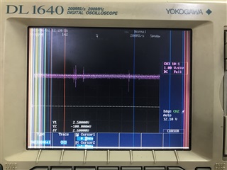
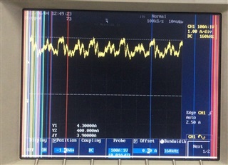
When I'm checking the waveform on TL431, I have seen there is noise over there. Please suggest which component I need to focus so that I can remove noise in this circuit.
Hi, Ye this is reference pin of TL431. At output side as per calculation I already connected 470uF capacitor. But still Noise is same when I'm using he shortest GND point.
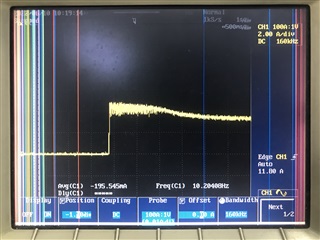
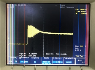
Hi, When I am connecting the battery at load side (V=48V). CC is working. Output current image is attached. There is noise while connecting the load. Pls suggest how i can remove the noise.
Thanks for your information. So does this noise only show when you connect battery? and does it disappear and would not show during battery charging, is it correct?
If yes, I think this noise comes from capacitive current spike. Adding an inductance and resistance to be a filter may be helpful, but it impacts efficiency. Does this short noise impact any system operation or out of system specification? If it does not impact system, maybe you could ignore it.
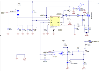
Would you please share me the schematic and how you connect battery to let me understand more about your questions?
Hi, While connecting the 48V battery at load side my CC is working but still waveform looks unstable. To control the sudden spikes I've tried to increase the value of capacitor at controller side. i.e. FB and VS side. Kindly support for the same so that I can complete the task as soon as possible.
Based on your waveform, it seems your feedback loop response is too slow to cause the oscillation.
You may try to modify compensation loop to speed up the loop response.
To increase Vs cap might impact VDS valley detection. It is not recommend to increase Vs cap a lot. And too big FB capacitance is also make slow response.
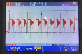
In my design when I check the MOSFET (Vds=800V. Id=17A), Drain to Source overshoot it is going more than 848V at 280V AC Input(Img. attached). In my design I already added snubber circuit (20K/2W & C=2.2nF & 10nF (parallel connected)).
Testing condition: Input= 280V AC, Output Voltage : 58.4V, 6A (48V Battery connected at output side)
Same
condition 1: Increased 2.2nF capacitor to 10nF
Condition 2: Remove 2.2nF capacitor
In both conditions overshoot is same. Kindly suggest how I can reduce the overshoot spike.


 Your early response will be valuable for me.