This thread has been locked.

If you have a related question, please click the "Ask a related question" button in the top right corner. The newly created question will be automatically linked to this question.

TPS65094: Power-up Sequencing

Part Number: TPS65094

Hi there,

I'm trying to set up a version of this where I modified your board to accommodate a high-frequency socket. So far, I've managed to get communication working and get an output on BUCK1, BUCK3, BUCK4, BUCK5, and BUCK6, although I'm experiencing a surprisingly high current draw resulting from BUCK6 which increases non-linearly as I modify the BUCK6VID register (0mA at output=0, increasing exponentially until around 300mA at 1.45V). BUCK

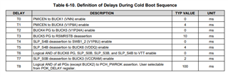
I'd like to ensure the startup sequence works how I think it does. First, VSYS turns on (I have 13V). Then the internal regulators should turn on, then the external regulators must come up, then PMICEN should turn to high. Is there any specific maximum timing delay constraint that must be met in order to ensure proper operation? If the external power were supplied through an external source such as two power supplies instead of using the suggested TPS51285BRUK, would the delay of manually starting those cause issues?

And about the blue arrows on the cold boot sequence on page 41 of the datasheet. Do those represent dependency? Could you elaborate a little more on those?

Kind regards,

Aaron

  • Hi Aaron,

    The timing diagram on page 41 of the datasheet covers most of the information on the power up sequence. VSYS needs to reach the 5.6V threshold first. Then the internal LDOs will activate (or if you are using an external supply for the 5V and 3.3V you should enable these outputs at this stage after VSYS). Then PMICEN needs to be asserted before the BUCKs and Load Switches can be enabled by future control signals. The only recommendation is that you make sure VSYS and your internal/external power supplies are stable before asserting PMICEN. There's no specific timing to hit in this regard but the order is still important.

    The only timings controlled by the PMIC are the factory programmed timings shown in Table 6-10 in the datasheet (pictured below). These timings can be seen on the power sequence chart, in between rail activations. The enable signals, shown in red text on the power sequence diagram, should be handled by your external SoC. The maximum timing for those enable signals will be determined by your SoC requirements, not the PMIC itself. If the SoC is looking for the next enable signal within 5 seconds then that would be your max timing limit. Since these timings are factory programmed there is no way to change them after production.

    The blue arrows do show dependency. They specify which signals are required before other signals can be asserted. For example, the internal LDO5 and LDO3V3 will not activate until VSYS reaches the 5.6V UVLO threshold. Or for the external supply case, the external 5V and 3.3V should not be enabled until VSYS reaches the 5.6V threshold.

    Just based on the datasheet it looks like BUCK6 has a typical use case of 7A. 300mA doesn't seem excessively large in this case, rather I would say it's on the lower end of the expected application.

    Regards,

    James

  • Thanks for the response. The BUCK6 concern was that there was no load on it and it was still drawing 300mA. We've determined that was due to a damaged part and is not occurring on other parts. Another question: is there a minimum load that should be used to attain proper feedback and functionality?

  • Hi Aaron,

    There's no minimum load for proper feedback. You could leave the BUCK6 output node floating if you wanted and the controller would still regulate. As long as you have the external components necessary for output stability (inductor and output capacitors), an external load isn't necessary for the rail to regulate properly.

    At very light loads the buck controllers will switch from PWM to PFM in auto mode (If you have a buck set to Force PWM mode it will not switch to PFM at light load). The picture below is from the datasheet:

    Regards,

    James