Hi,
Let me ask the following questions in the thread below.
e2e.ti.com/.../4090314
Customers are investigating battery leak current when VBUS is connected to supply VSYS.
I got the following answer in a previous thread.
>The battery voltage is not used to power the converter, only power from VBUS.
However, when the battery leak current path was investigated, the following was found.
・In the case of ”VBUS=5.14V ,VBAT=4.86V, Charging stopped state” condition, quiescent battery current increased. The actual measurement is about 380 μA.
・At this time, the input current to the BATP pin was 2.4uA.
・VSYS is no load. And VSYS voltage was set to 7V and no leakage current was confirmed via the BATFET diode.
From the above background, the battery leak current is clearly used in the internal circuit.
And Battery leak current is reduced by using Hi-Z mode.
From these facts, it can be seen that the battery leak current is used for the internal converter.
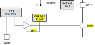
Could you tell me the details of the current value input to the BAT pin under the condition that VBUS is connected?
I would like to know how the battery leak current is consumed when charging is stopped with the VBUS connected.
Regards,
Yusuke