This thread has been locked.

If you have a related question, please click the "Ask a related question" button in the top right corner. The newly created question will be automatically linked to this question.

LM5164-Q1: Audible noise at light load

Part Number: LM5164-Q1
Other Parts Discussed in Thread: LM5146DESIGN-CALC

Hello,

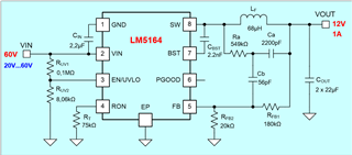
We are using following circuit  with components as given in it and we have some audible noise on pcb (capacitors) at light load conditions.

NOISE:

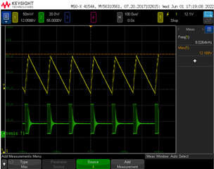
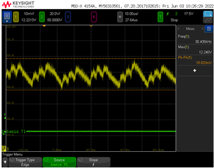
Output voltage:  Measurements shows that DCM causing +/- 50mV output ripple at around 8 kHz frequecy and ceramic capacitors producing some audible noise.

Ripple Generation Method

After some investigation we have found out that our CB capacitor value is not correct.

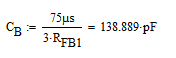
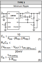
But LM5146DESIGN-CALC design tool shows 56pF. Is design tool giving wrong values?

Changes:

We have changed CB as 220pF and CA as 3,3nF and measured the output again.

Now output ripple is around 20mV and there is no audiable noise on pcb.

Switching:

But switching seems to be not normal. There is some spikes between t_on phases.

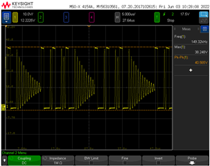
Is this  switching behaviour normal?

Could you please also confirm that changed capacitor values (3,3nF and 220pF) won't cause any problem.

Thank you for your support.

  • Hello,

    The calculator calculates for 20mVpp ripple injection. We advise a minimum of typically 12mV.

    The component values are calculated for the nominal input voltage in the case the customer is willing to tolerate increased output ripple for a transient vin condition.

    If you want to ensure constant frequency operation, with minimal output ripple across your vin range, then, we would want to consider calculating for your ripple injection components at your minimum vin, ensuring that the injected ripple is greater (or equal) than 12mV.

    Putting 20V as the nominal input voltage for the calculator to obtain ripple injection components for 12mVpp injected ripple, I obtain:

    Ra=604kOhm, Ca=3.3nF (increased to have smaller Ra) and Cb =56pF.

    I believe your selected component values of Ca-3.3nF and Cb=220pF to be OK. The difference between computation in the datasheet and the calculator is most likely the selected settling time for Cb equation, which is application specific.

    I would confirm though Ra ~604kOhm, as the waveforms you shared seem to be a result of insufficient ripple injection, with both Ra and Ca determining the amplitude of the ripple injection.

    Here is a nice article on ripple injection in COT devices if you are interested in learning more about the theory.

    https://www.ti.com/lit/an/snva874/snva874.pdf?ts=1654283280124&ref_url=https%253A%252F%252Fwww.google.com%252F