A related question is a question created from another question. When the related question is created, it will be automatically linked to the original question.
If you have a related question, please click the "Ask a related question" button in the top right corner. The newly created question will be automatically linked to this question.
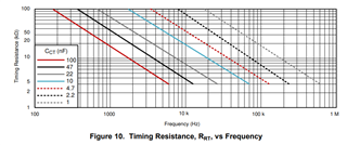
Yes you are right. it should increase Cct to get the same frequency.
The recommended range of timing resistor values is between 5 kΩ and 100 kΩ; the recommended range of timing capacitor values is between 1 nF and 100 nF.