This thread has been locked.

If you have a related question, please click the "Ask a related question" button in the top right corner. The newly created question will be automatically linked to this question.

TPS65023: Pin assignment clarification

Part Number: TPS65023

Hi 

Query-1:

We plan to use MPN # TPS65023QRHARQ1 to connect with i.mx6ULL nxp's processor. We have gone through the pin assignment and have a query with pin#27 "RESPWRON". 

Can we connect this pin to the i.mx6ULL POR pin(P8)? As per the i.mx it's Power on reset functionality in the SNVS domain and has an internal Pull-up.

Query-2:

i.mx pin(T9) "PMIC_ON_REQ" is connected to which pin of PMIC?

Appreciate in advance. 

  • Hello Viral,

    Thank you for the post. We should be able to respond by the end of the week.

    Regards,

    Alex

  • Hi Viral,

    Thank You for using E2E! Below are the responses to your questions. Please let us know if you need anything else.

    Can we connect this pin to the i.mx6ULL POR pin(P8)?

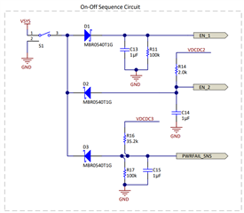
    The i.MX 6ULL datasheet requires the POR_B signal to be immediately asserted at power-up and to remain asserted until after the last power rail reaches its working voltage. The RESPWRON signal on the TPS65023 is generated according to the power-good comparator of the VRTC rail so it is help low when power is initially applied to the PMIC but it gets released when the VRTC LDO reaches its power-good threshold (the timing to release the RESPWRON signal is also defined by the external capacitor at the TRESPWRON pin). Since VRTC LDO is the first rail going high in the power-up sequence, the RESPWRON is not ideal to drive the POR_B on the processor. Instead we recommend using the PWRFAIL output to drive the SRC_POR_B signal on the i.MX6ULL. This would require the PWRFAIL_SNS signal (input for the comparator driving the PWRFAIL) to be included in the external ON/OFF sequence circuit as described in the Apps note at the following link: Power Supply Design for NXP i.MX 6 Using the TPS65023.


    i.mx pin(T9) "PMIC_ON_REQ" is connected to which pin of PMIC?

    The "PMIC_ON_REQ" signal could be used to drive the start of the external ON/OFF sequence circuit. For example, it can be used to drive the S1 switch in the circuit shown below. This capture was taken from the same Apps note that was referenced in the first question.   

    Thanks,

    Brenda

  • Thanks, Brenda, one more follow-up query from your answer is as follows:

    Connecting PWRFAIL to PMIC_POR makes sense, but I wonder then what shall be the pin assignment for the RESPWRORN pin (pin 27 on PMIC)?

  • Hi Viral, 

    Since the RESPWRON is generated based on the power good for the VRTC (VDD_SNVS_IN), then it can also be combined through logic with the PWRFAIL to drive the POR_B on the i.MX6 with a buffer. Please note the HOT_RESET functionality on the TPS65023 PMIC is also linked to the RESPWRON pin. 

    Thanks,

    Brenda

  • As a part of the FW integration, we did the below changes.
    Changes are done in the kernel(4.9.88):
    2. Enable the PMIC in config using CONFIG_REGULATOR_TPS65023=y
    Error message:
    i2c i2c-0: IMX I2C adapter registered
    i2c i2c-0: can't use DMA, using PIO instead.
    vdd_mpu: failed to get the current voltage(-6)
    tps65023 3-0048: failed to register tps65023
    i2c i2c-3: IMX I2C adapter registered
    i2c i2c-3: can't use DMA, using PIO instead.
    Here I have confirmed that the HW connection is good and PMIC is responding at the time of the u-boot communication. 
    Any direction on fixing this issue?
  • Hi Ankur,

    Brenda should be able to respond by early next week.

    Regards,

    Alex

  • Thank you Alex,

    For more information, I am able to talk with the PMIC using the Linux i2c tool.

    But With the TPS65023 driver, the PMIC is not responding. 

    TPS65023 Driver : https://elixir.bootlin.com/linux/v4.7.3/source/drivers/regulator/tps65023-regulator.c

    DTS file:

    &i2c4 {
            clock-frequency = <100000>;
            pinctrl-names = "default";
            pinctrl-0 = <&pinctrl_i2c4>;
            status = "okay";
    
    
            pmic: tps65023@48 {
                   compatible = "ti,tps65023";
                   reg = <0x48>;
    
                   regulators {
                           sw1a_reg: VDCDC1 {
                                   regulator-name = "vdd_mpu";
                                   regulator-always-on;
                                   regulator-min-microvolt = <1350000>;
                                   regulator-max-microvolt = <1500000>;
                           };
    
                           VDCDC2 {
                                   regulator-name = "vdd_core";
                                   regulator-always-on;
                                   regulator-min-microvolt = <2900000>;
                                   regulator-max-microvolt = <3300000>;
                           };
    
                           VDCDC3 {
                                   regulator-name = "vdd_io";
                                   regulator-always-on;
                                   regulator-min-microvolt = <1350000>;
                                   regulator-max-microvolt = <1450000>;
                           };
    
                           LDO1 {
                                   regulator-name = "vdd_usb18";
                                   regulator-always-on;
                                   regulator-min-microvolt = <1750000>;
                                   regulator-max-microvolt = <1820000>;
                           };
    
                           LDO2 {
                                   regulator-name = "vdd_usb33";
                                   regulator-always-on;
                                   regulator-min-microvolt = <3200000>;
                                   regulator-max-microvolt = <3300000>;
                           };
                   };
           };


  • Hi Ankur,

    Since this is a software question, I'll be reassigning the E2E to the right person. 

    Thanks,

    Brenda

  • Hello,

    I do not see anything obvious which would cause the error.  Can you confirm that the voltage levels match with the PMIC?  Also, can you share where the error message "vdd_mpu: failed to get the current voltage(-6)" is coming from in the source code?

    Regards,
    Chris