This thread has been locked.

If you have a related question, please click the "Ask a related question" button in the top right corner. The newly created question will be automatically linked to this question.

BQ25505: Nano-power harvesting PMIC with Current limit function

Part Number: BQ25505
Other Parts Discussed in Thread: TPS62736, , BQ25504, BQ25150, BQ25100, BQ24210

Hi,

I am designing a circuit to harvest nano and micro watts from a (3 Vmp, 50mA Imp) solar cell and charge a 4.1V max battery. 

When there is enough light, the current to the battery should not exceed 40mA so the PMIC shall have current limiting functionality as well. This is important for scenarios when the battery is depleted to low voltages. For example solar cell is generating 3Vx50mA = 150mW, and if battery voltage is 2V, it can be charged up to 75mA assuming PMIC 100% efficiency. 

Do you have any chip to recommend that has nano and micro power harvesting with high efficiency, and at the same time can limit charging current to the battery if excessive power is available? 

Thanks 

  • Hi Kaveh,

    Unfortunately, our harvesting chargers do not have current limit.  You might consider a 2 chip solution using the BQ25505 solely as a boost converter to provide at least 4.2V followed by a buck converter set to 100mA with 50mA output current limit like TPS62736.   I realize the 50mA output current limit is a slightly higher than your desired 40mA but TI doesn't have a buck converter with lower current limit. 

    Regards,
    Jeff

  • Thanks Jeff. How about using BQ25505 to charge my battery and put a current limiting diode like CL40M45 in between BQ25505 and my battery?

  • Hi Kaveh,

    I'm not familiar with those.  If you adjust the VBAT_OV voltage to accommodate the diode drop and live with the power loss across the diode, in theory it should work.

    Regards,

    Jeff

  • Thanks Jeff. Aside from the current limit function, battery manufacturer recommends to use a constant current constant voltage mechanism to charge my battery. Can I use this chip directly between solar cell and battery to charge the battery considering this matter? 

  • Kaveh,

    The BQ25505 only provides constant voltage charging.  The charge current is delivered in pulses so should be safe and not age the battery but is technically not constant current charging.

    Regards,
    Jeff

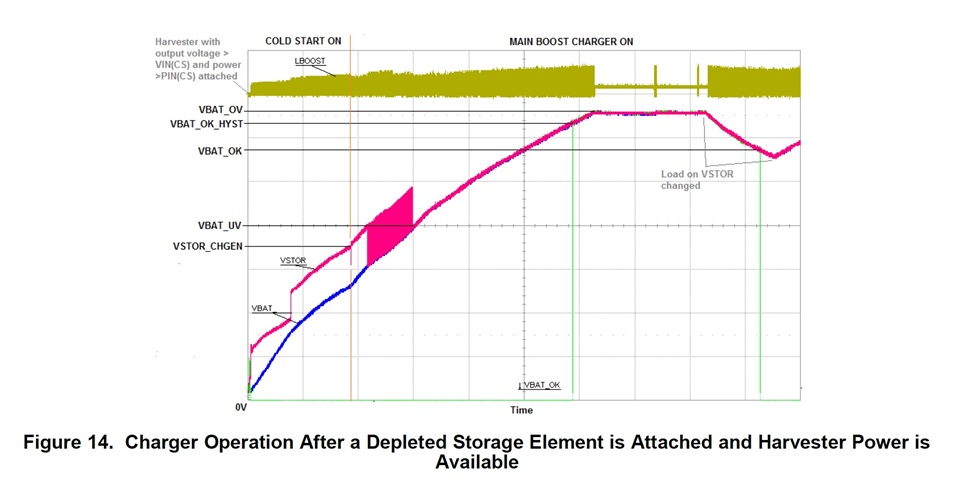
  • Thanks Jeff. In the datasheet Figure 14, there are curves for VSTOR, VBAT and inductor pick pulse currents charging the battery. 

    Considering the pulse current curves, I can see when the battery is fully depleted, pulse current picks are close to 0 and as the battery voltage rises and battery get charged the amplitude of these pulse currents rises. Does the duty cycle and frequency of these pulses also change as battery voltage rises? How is that change? Does frequency and duty cycle increase as well, or they decrease? 

  • Hi Kaveh,

    Because of the hysteretic/PFM discontinuous mode topology, there is no closed loop equation for switching frequency or duty cycle. Both will change as the output power or input power changes.  Max switching frequency is 1MHz if a low impedance source is attached.  Max low-side FET on-time is somewhat predictable since the FET turns on until the inductor current reaches the max current = 300mA max, so using v = L *di/dt, dt=L*300mA/(VSTOR-VINDCavg).  But the switch cannot turn on again until the input capacitor has recharged above the MPP threshold.  And it will not turn on again if VBAT=VBAT_OV. 

    Regards,

    Jeff

  • Thanks Jeff. What I am trying to understand is the DC charging current into the battery as the voltage rise from 0 to 4.1V. 

    From the current curves in figure 14 above, initially pick pulse currents are minimal and during operation of the hysteric charger, VDC_IN is clamped to 600mV. So charging current is somewhat limited. 

    And from the curves, during boost converter operation after transition to second mode (PFM?) there is a rise in pulse currents picks. 

    My input power is constant 135 mW. and VBAT max is 4.1V. 

    Theoretically when battery is fully depleted, it should charge with infinit DC current to maintain Pin =135W x 90%=Pout=0v x I(DC). But that is not the case. 

    Theoretically, when battery is about fully charged, Pin = 135W x 90%= Pout = 4.1v x 30mA

    From the curves, pulse current picks are maximum at the end of charge cycle when VBAT = 4.1V and minimum when battery is fully depleted. 

    So I can conclude that charging current never exceed 30mA?

  • Hi Kaveh,

    The absolute maximum charge current for any DCM, peak inductor current controlled boost converter running at 50% duty cycle and with low output source (i.e. not a solar panel), is 0.5*Ipeak = 0.5*300mA = 150mA.  From the high output source like solar panel, the charger limits average input voltage to MPP%*VOC.  If you assume the panels, ISC is the max output current (which is an over estimation) then max input power is MPP%*VOC*ISC.  Then, using the datasheet efficiency curves, you can estimate max output power as eff = VBAT*IBATavg/(MPP%*VOC*ISC).

    Regards,

    Jeff

  • Thanks Jeff. 

    Are there simulation models and maybe examples in TI-Tina for simulating BQ25505 that I can use.

  • HI Kaveh,

    Unfortunately, the TINA-spice model for the parent device, BQ25504, is no longer supported and was removed from the library.  It only provided very basic operation so likely would not be much help.  Another customer told me that they found it on the web but I do not know where.

    Regards,

    Jeff  

  • I found BQ25150 that could be used after BQ25505. It does voltage regulation and has battery charging current limiting function. 

    What is your opinion about it? 

  • Hi Kaveh,

    Seems reasonable.  Please keep in mind that the BQ25150's VINDPM needs to be set to prevent collapsing the BQ25505 VSTOR=VBAT output.

    Regards,
    Jeff

  • Thanks Jeff. BQ25150 I2C programming needs to happen once, right? It has an EEPROM memory to keep ICHG, ITERM, etc values once these values are programmed. 

  • Hi Kaveh,

    No.  All of our I2C chargers reset the I2C registers when the watchdog timer expires or the device has both input power and the battery removed.

    Regards,
    Jeff

  • That is not good.

  • Kaveh,

    We have standalone chargers like BQ25100 family with resistor set ICHG/ITERM.  I recommend one with resistor settable VINDPM like BQ24210.

    Regards,
    Jeff 

  • The Quiescent current for BQ24210 seems too high for my application. 

    Is bq25100L already in stock? 

  • Kaveh,

    The BQ25100L is a product preview and has not been released.

    Regards,
    Jeff

  • Hi Jeff, 

    If you remember, I was concerned about BQ25505 battery charging current when battery is fully depleted. Our battery should not be charged above 40mA. 

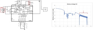
    We have done a slow I-V sweep at BAT_SEC node. My VBAT_OK is 3V and VBAT_OV=4.1V. Pin= 120mW constant.  

    Battery current-voltage curves look normal to me and I assume the current level changes about 1.5V is associated to BQ25505 coming out of cold start and turning main boost converter on. 

    But I do understand current oscillation or ripples between battery voltages 3V to 4V. Is that due to BQ25505 control loop response?


  • Hi Kaveh,

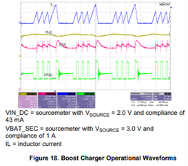
    This charger is purely hysteretic so there is no feedback loop instability.  What is likely happening is the input voltage is dropping below the MPP point, the charger stops switching (outputting charge current) briefly and then starts again when the input capacitor recharges above the MPP threshold.  This results in pulse charging.  If you have an oscilloscope, I suggest looking at VIN_DC, LBOOST, VBAT voltages and IBAT (not shown below) if you have a current probe. 


    Regards,

    Jeff

  • Thanks Jeff. Is it Vmpp dropping due to connection to C_STOR cap load above 3V? Because below 3V there are no ripples. 

  • As the output voltage increases so does the required output power.  If the input source's output impedance is too high, the input capacitor gets drained.

    Regards,

    Jeff

  • Thanks Jeff. In my design with BQ25505 I have set VBAT_Ok = 3V and VBAT_OK_Hyst = 3.1V. 

    At initial power up, is it suggested to connect solar cell first or the battery and why? 

    Considering answer above, which thersholds VBAT_Ok or VBAT_OK_Hyst does BQ25505 consider at power up, to connect/disconnect the load to/from the battery?

  • Kaveh,

    VBAT_OK output is only a signal (i.e. it doesn't control control any other chip function) except for the MUX drivers.  100mV is a bit low and you might see some chatter as the battery rises or falls between 3.0V to 3.1V.

    At power up, the internal PFET between VBAT and VSTOR always allows current flow from VSTOR to VBAT through the body diode.  However, the charger was not design for battery attach while input power is attached and so the PFET will not turn on.  So, you must attach a battery only after VSTOR and VBAT <100mV (i.e. no power attached).  

    Regards,

    Jeff

  • So we should attach battery first and then the solar cell, right? 

  • Hi Kaveh,

    Yes.

    Regards,

    Jeff