


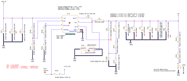
Vout (VS1) in the circuit diagram below is used as the voltage to drive the solenoid.
The solenoids themselves will be connected in multiple connections, and they will all be turned on at PWM:20kHz.
We checked the waveform of VSW at the maximum load (peak 1.2A), which is currently assumed, and found a part of oscillation.
1ch = voltage indicating solenoid On
3ch = Vfb
4ch = Vsw
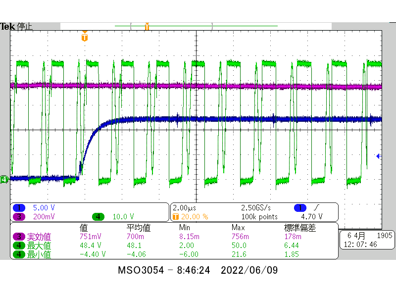
We thought that the period that looks like oscillation at Vsw of 4ch is about 500kHz.
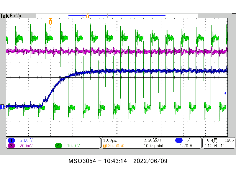
We tentatively changed the DCDC switching frequency as follows and re-measured it, and the Vsw oscillation disappeared.
Before correction: DCDC switching frequency = 500kHz / R125=27k , R129=18k
After correction: DCDC switching frequency = 1.5MHz / R125=15k , R129=0
I would like to get advice on the following.
What should I pay attention to in order to avoid oscillation inside the IC?
When C100 = not mounted, "the ripple of Vfb and the oscillation of Vsw were synchronized".
Therefore, C100 = 1000pF was used to reduce the ripple of Vfb, and the ripple of Vfb was suppressed, but Vsw oscillated.
Therefore, we would like to know where we should pay attention.
What should we refer to when deciding the switching frequency of DCDC considering the expected load fluctuation (approximately 20KHz)?
We would like to know how to reduce the overshoot/undershoot of VSW that is expected when the switching frequency of DCDC is increased (in particular, we would like to know how to do this other than changing to a fast recovery diode).
Best regards.
