Other Parts Discussed in Thread: BQ51013,
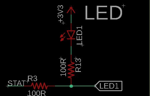
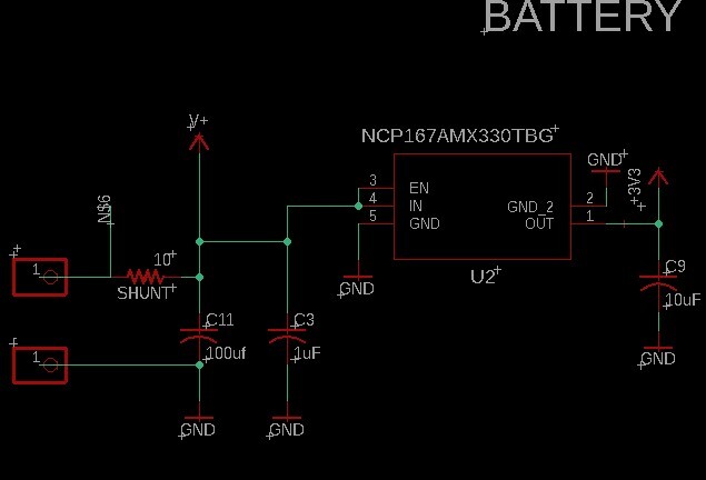
We have designed a receiver board (schematics included for the QI related portions) originally was tested with default values for Rilim and Rterm but later went with values from this post https://e2e.ti.com/support/power-management-group/power-management/f/power-management-forum/1096183/bq51050b-resistor-values-for-bq51050brhl?tisearch=e2e-quicksearch&keymatch=BQ51050b, as our requirements were similar.


 I performed tests using an 18650 cell as well as the simple battery emulator referenced in the design guide for this IC. (2 power resistors, a diode, and a shunt)

We are testing 3 different coils, with specific C1 and C2 values that were calculated for each.

We are using an Anker PowerWave pad for the TX and our custom PCB for the RX (very compact design)
*update* Just received a TYLT Vu-Solo TX to re-test with.

AC2 voltage is usually between 8 and 20V.
Rect does at times seem low and is even under the 2.7V which to my understanding means that it will not try to communicate or adjust the voltage to just over battery voltage before enabling OUT.

I have managed to get rect above 2.7V (about 3V with 42.2K ROS attached using our larger more standard sized coil and 20Vp-p on AC2) This was with Term resistor and our larger battery cap removed.
With this test I see a ping every 500ms, and rect tapers off after the ping, which lasts  about 100ms, with another transmitter I get the same behavior but a longer ping of about 200ms.

Out never turns on, rect voltage is not moving and I don't see any apparent communication. I've tried adjusting the COMM capps from .022 to .033 and .046 Uf. with no difference.

I did however see some movement with ROS resistor removed. In that case I saw the Rect voltage climb as the AC2 voltage changed (became lower) and it held steady just above battery voltage but there was no
output or indication on the TX or RX of a proper connection.

Without the battery (I know it won't work without the battery) the Charge LED will blink dimly. With the battery though there is no light on the LED at any point.

I have also tried adjusting RFOD from 200 to 220 to 435 ohms.

The Anker Transmitter with the coil placed on top or even hovering slightly above when in the middle does flash it's LED which according to the manual is an FOD issue.

The Temperature sensing is disabled with a 10K resistor to ground.

We do not use wired charging and EN2 is left floating (I've read this should be OK, let me know if I am wrong)

I also just received a decade box to attempt to adjust the RFOD resistor. I noticed I could get the blinking on the Anker transmitter to stop and also raise the Rect voltage by increasing ROS, I still don't see output though.
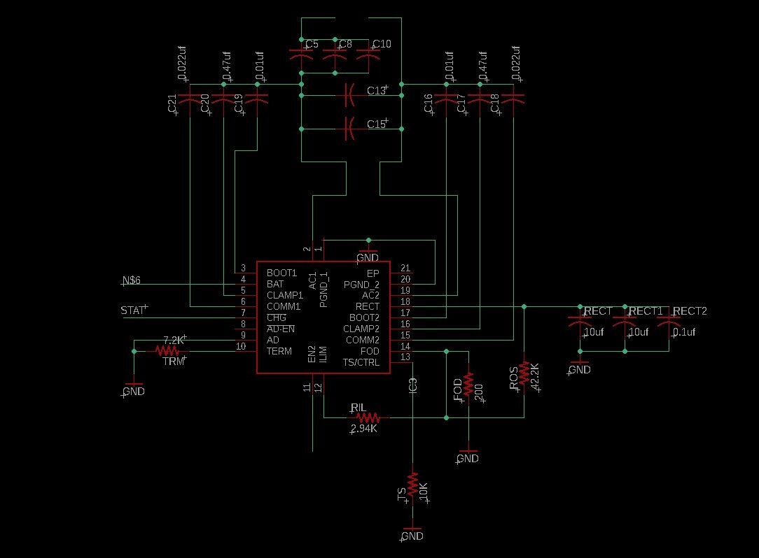
Coil details: Large Sensor Coil: 26.565uH ~21mm R = 0.89 Ohm 95nF = C1 (.047uF + .033uF + .015uF) 1nf = C2 (820pF + 180pF) Small Sensor Coil: 12.48uH ~17mm R = 0.32 Ohm 203nF = C1 (.15uF + .039uF + .015uF) 2.1nF = C2 (.0018uF + 330pF) Other(standard QI coil): 11.65uH ~35x45mm 217nf = C1 2.2nf = C2 Any help or advice on what to look at next would be appreciated, I'm going to try and adjust RFOD but if anything seems out of place do let me know. Our design is also quite compact and we would be happy to share our layout files in a non-public ticket.
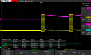
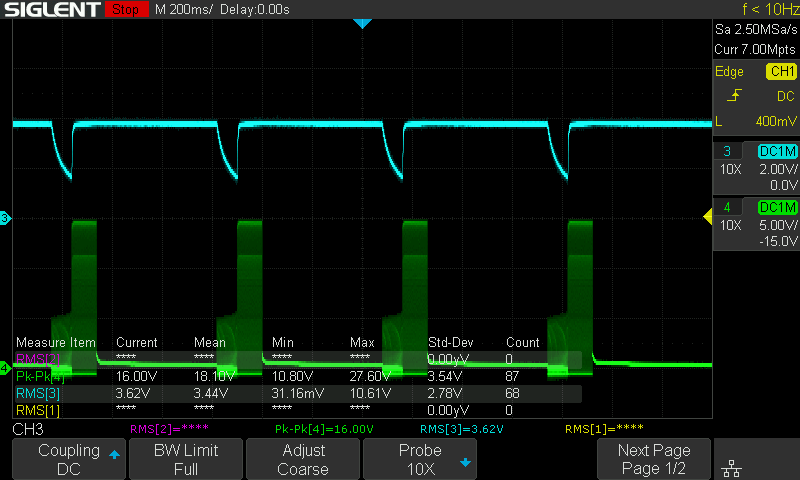
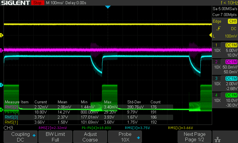
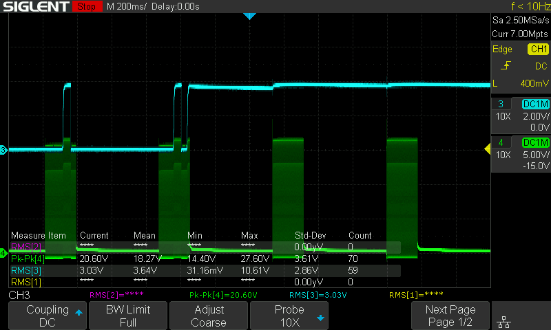
Some scope captures: (let me know if/what specifically I should be trying to capture and I'll upload it)
 <- No battery.
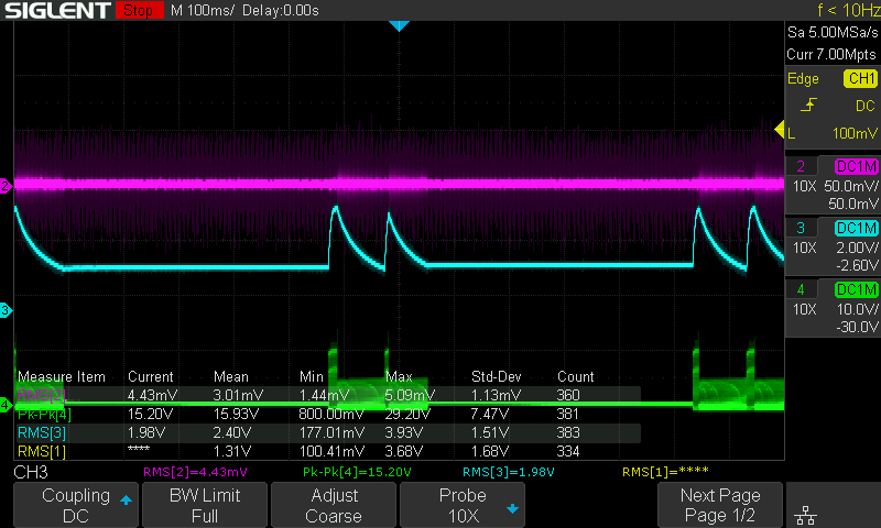
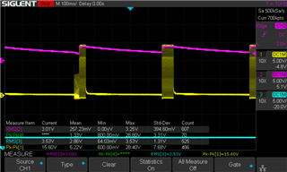
 No ROS
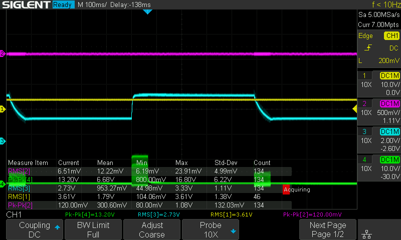
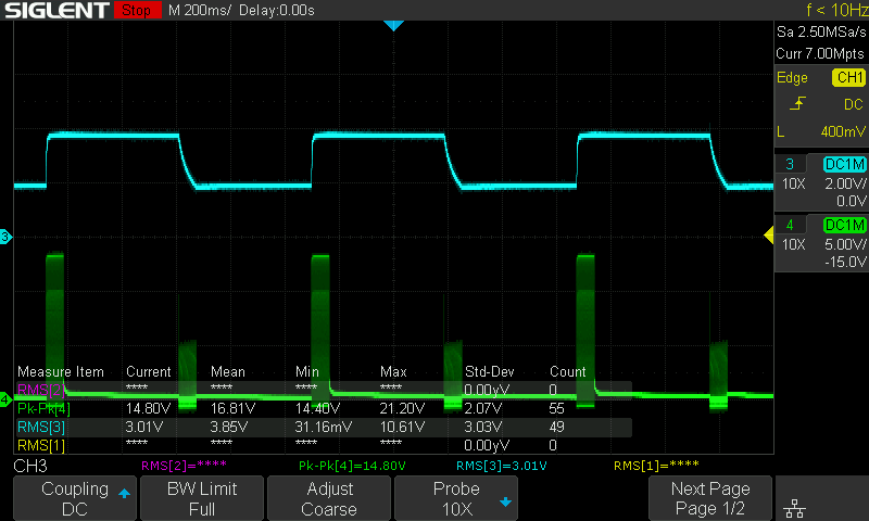
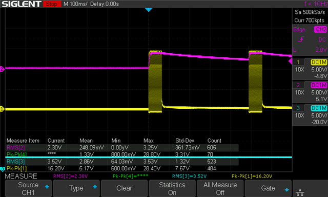
 <- Normal ->
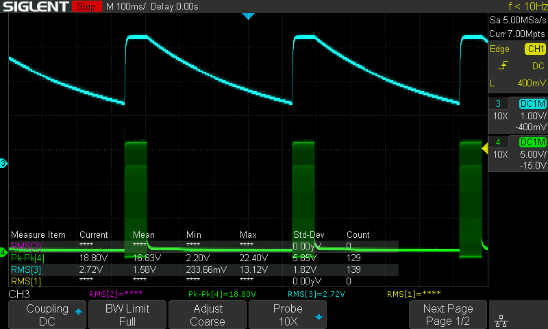
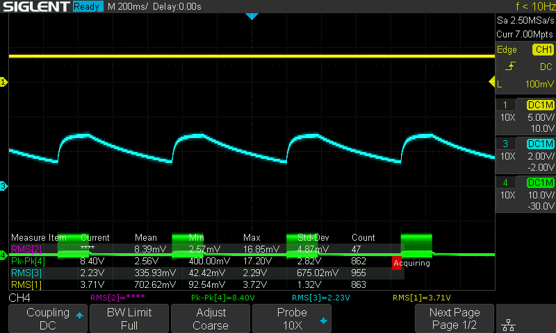
 <-(?)
<-(?)
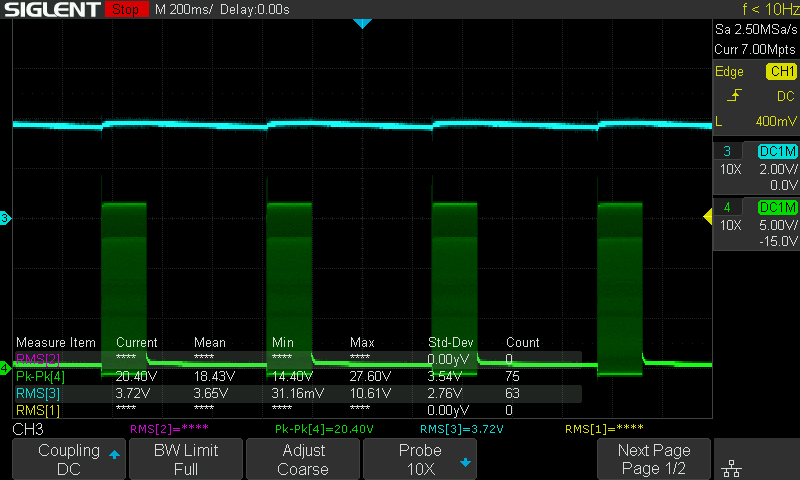
Most of those that had above 2.7V on Rect had ROS removed before I found I could adjust ROS to increase it. These are some of the waveforms I've been able to capture.
Thanks in advance.