This thread has been locked.

If you have a related question, please click the "Ask a related question" button in the top right corner. The newly created question will be automatically linked to this question.

TPS2H160-Q1: TPS2H160-Q1 Open-Load Detection discussion

Part Number: TPS2H160-Q1

Hi Team

We have discussed the same topic before! (See E2E link below)
Now there are new questions that need your help ,THX

https://e2e.ti.com/support/power-management-group/power-management/f/power-management-forum/1087587/tps2h160-q1-please-help-confirm-this?tisearch=e2e-sitesearch&keymatch=TPS2H160#

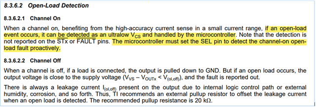
>>>Because according to the description in the datasheet, Channel ON does not need to pull up 20K ohms.
Although FAULT will not be output, the MCU can still detect it through other settings.

Is this narrative as we understand it?
If so, how should it be implemented?

  • Hi Kygo,

    The TPS2H160-Q1 has two versions, A and B. This question only pertains to version B as this version of the device has a current sense pin.

    The current sense pin acts as a current mirror for the current passing through the NMOS. When the NMOS is in an “on” state meaning the switch is closed, the switch expects to see the same voltage on both the source and drain. However, if there is an open load, there will be no current flow. This is reflected in the ultralow Vcs at the current sense pin. A short to the battery and reverse polarity will also result in ultralow Vcs at the current sense pin. Regardless, reading the voltage at the current sense pin will help you to determine any problems with the circuit design.

    regards,

    Quinn

  • Hi Quinn

    Thanks for your reply

    TPS2H160-Q1 versions B can communicate with the MCU through the current sense pin (as shown in the figure below).

    OUT1/2 can detect OPEN load or Short to Gnd, right?

    What is R、C recommended value? THX

  • Hello Kygo,

    For version B, the FAULT pin is a global fault and it monitors faults for all channels. When it detects a fault, the FAULT pin is pulled down to GND. The CS pin can detect faults on a specific channel based on the voltage level of the SEL pin. SEL low (CH1), SEL high (CH2). The CS pin reports faults by a pullup voltage of VCS(H).

    As far as the resistors and capacitors between the CS pin and the MCU, these are design choices. The RCS resistor is used to set the current sense range and can be calculated using (VCS x KCL) / IOUT. The other resistor is a protection resistor and the capacitor is a filter capacitor, again these are design choices but common values are 10kΩ and 100pF to 1nF respectively.


    Regards,

         Quinn