A related question is a question created from another question. When the related question is created, it will be automatically linked to the original question.
If you have a related question, please click the "Ask a related question" button in the top right corner. The newly created question will be automatically linked to this question.
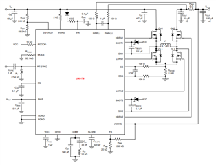
You would like to know how to calculate the power dissipation of the LM5176 device only - not of the full application (incl. e.g. the MOSFETs) - right?
PS: it looks like you have attached a picture but I can not open it - can you check this.
there are some components which contribute to the power dissipation of the LM5176 which needs to be considered here:
1. Losses on VCC LDO
- device operation: supplied from Vcc * Device current IQ (see datasheet for both values)
- current required to drive the low side FET (this needs to be considered as this current is taken from the Vcc, the high side FET are driven from the current of the charge pump on BOOTx / SWx) Calculate the Current required to drive the Gate of the two load side FETs - this will change for the different operation conditions (BUCK/BOOST)
Both of this two current above are supplied by the LDO to generate the Vcc voltage. So there is an additional loss of:
[(Vin or VBias) - Vcc ] * Sum of Currents[FETs and IQ ]
2. Losses on Gate driver - this will change for the different operation conditions (BUCK/BOOST)
Current required to drive the Gate lines of the 4 power FETs: sum of [ P_Loss_x = R(xDRVx) * I_drive_x ^ 2 ]
(Losses on Gate driver - this will change for the different operation conditions (BUCK/BOOST)
Current required to drive the Gate lines of the 4 power FETs: sum of [ P_Loss_x = R(xDRVx) * I_drive_x ^ 2 ]
R(xDRVx) : see datasheet)
In this equation you considered 4 MOSFET operate at a time, but in practically any operating condition( Buck or Boost) at a time only 3 MOSFETs are turning on and 1 MOSFET continually off .
can you confirm in the equation can we considered 4 or 3 Mosfet.
you are right this will be identical for both mode with having 3 MOSFETs switching.
If you have identical MOSFETs on the BUCK and BOOST leg then this is identical. If there are different MOSFETs on the BUCK and BOOST leg then this could be different as well