This thread has been locked.

If you have a related question, please click the "Ask a related question" button in the top right corner. The newly created question will be automatically linked to this question.

TPS536C7: Loop compensation parameters to improve phase margin in FUSION_DIGITAL_POWER_DESIGNER

Part Number: TPS536C7

Hi,

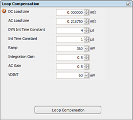
I'm using TPS536C7 multiphase PWM controller. Using the loop compensation parameters as shown in the below image, I'm getting around 22° phase margin. Please suggest on how should I change these parameters to achieve phase margin greater than 65° phase margin.

  • Hi Abhishek,

    Lower AC Loadline (ACLL) allows higher bandwidth and faster transient response. But setting the ACLL to a very low value may lead to low phase margin and loop instability.

    Also, can you please describe the setup that you are using to take the measurements.

    Thanks & Regards,

    Aishwarya

  • Hi Aishwarya,

    We are using a Frequency response analyser to measure the phase and gain margin. 
    Kindly suggest the right values for all the above parameters with which we can get us at least 65° phase margin.

    Also, if you could provide a guide for tuning these parameters for any power supply using similar controller.

    Also, how much can we increase the AC load line value safely. After changing value from 0.2031mOhm to 0.25mOhm, phase margin increase from 23 to 24° only.

    Thanks & Regards,

    Abhishek Harsh

  • Hi Harsh,

    We cannot give the accurate parameters as the PM will also depend on your PDN. However I can provide some guideline for tuning these parameters, which are as below:

    1. AC LL- Lower ACLL allows higher bandwidth and faster transient response. Setting the ACLL to a very low value may lead to low phase margin and loop instability. It is desirable to keep the ACLL & DCLL values closer to each other for control loop to function properly.

    2.  Integration Time Constant- Lowering the integration time constant increases the DC gain and speeds up the settle time during transient response. Increasing the integration time constant improves phase margin.

    3. Integration Gain- Lowering integration gain increases the settle time during transient response.

    4. AC Gain- Raising the value of AC gain accelerates the transient response

    5. Dynamic Integration Time Constant- Increasing the dynamic integration time constant and reducing the VDINT decreases undershoot during high repetitive load transient.

    Please do not go to the extremities of these parameters to avoid instability.

    Thanks & Regards,

    Aishwarya