This thread has been locked.

If you have a related question, please click the "Ask a related question" button in the top right corner. The newly created question will be automatically linked to this question.

BQ25895: Question about BQ25895

Part Number: BQ25895

Hi

I have many questions while using BQ25895.

1. What are the conditions for the charging current to set 5A?

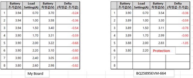
2. When the battery is connected and LOAD is applied to the SYS, the BATTERY voltage drops as shown below.

   Is it right that the battery voltage drops if load is applied to the sys?


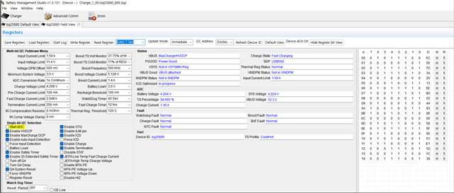
 3. If only 9v is entered in the vbus and there is no D+, D-, it is set as below, is it correct?
The reason why D+,D- doesn't have any value is because it's supplied by wireless charging.

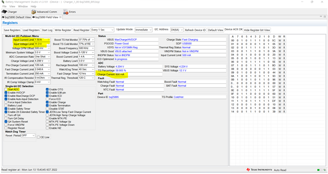
4. When charging with an adapter that supports MaxCharge, the limit is 11.3V and 1.5A , but the actual charge is 800mA.

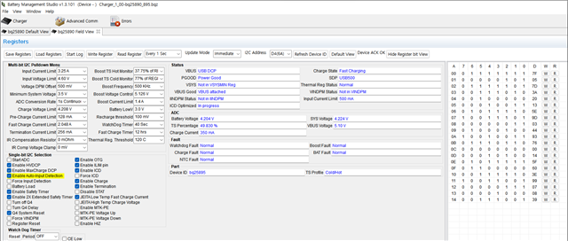
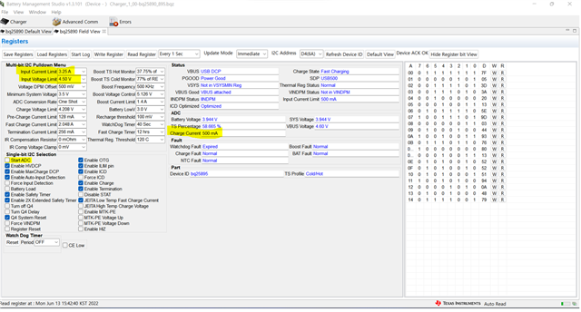
5. When charging with an unknown adapter , the limit is 4.5V and 3.25A , but the actual charge is 500mA.

Thanks

  • Hi David, 

    1) For charging at 5A you need to use a high voltage input adapter, then for register settings ensure input current limit (REG00) is set to a high enough value and ICHG (REG04) is set to 5A. You should also confirm the ILIM pin setting is not lowering your current limit, as the input current limit will automatically be the lower of resistor setting at ILIM pin and register setting. 

    2) Can you please provide more information on your observations. When you mention battery voltage is dropping where is that being measured? is it from the BAT pin test point on the EVM? Do you also have input power connected or is this test in battery only mode? It would also be helpful to see all register settings and status when you observe the drop in battery voltage due to system loading. 

    3) If you do not plan to use D+/D- detection I would recommend turning off D+/D- detection by setting AUTO_DPDM_EN = 0 (REG02 bit 0). You can also disable Maxcharge and HVDCP, both in REG02, as these are adapter handshakes performed via D+/D-. 

    4)There are two things to note based on the registers provided. Since the battery voltage is almost fully charged at 4.2V the device is in the constant voltage part of the charge cycle. You can expect the charge current to reduce from the fast charge setting during this portion of charge. Secondly, the input current optimizer (ICO), which is enabled/disabled via REG02 bit 4, is shown as still in progress. When the ICO is in progress the current limit is automatically 500mA and this status is read via REG13. 

    5) Based off the registers values provided the device is in IINDPM and this is why it can only charge at 500mA. It appears the ICO set the input current limit to 500mA based on REG13 status. First I would confirm your unknown adapter can actually operate up to 3.25A, then you can look to disable the ICO. With ICO disabled the actual input current limit will be based on your 3.25A setting on REG00. 

    Best Regards,

    Garrett

  • Hi Garrett

    Thanks for your support.

    I have additional question.

    I am comparing and EVM(BQ25895EVM-664) provided by TI with the board I made.

    I connected the same adapter(MAXCHARGER) and battery(18650), but there is a difference as below

    1. EVM: MAXCHARGER/HVDCP , VBUS:12.3V, Charger current:1.45A


     2. My board : USB DCP , VBUS:5.1V, Charger current:350mA


    Why doesn't my board recognize MAXCHARGER?

    Which part should I review?

    Thanks

  • Hi David, 

    Detection of MAXCHARGE/HVDCP input adapters is done via the D+/D- pins on the BQ25895. I would recommend comparing your boards schematic and wiring in regards to the D+/D- pins to how they are implemented on the BQ25895EVM. The BQ25895EVM schematic is located in the EVM user guide, which can be downloaded via TI.com. (https://www.ti.com/tool/BQ25895EVM-664)

    Best Regards,

    Garrett