This thread has been locked.

If you have a related question, please click the "Ask a related question" button in the top right corner. The newly created question will be automatically linked to this question.

BQ25181: PMU Design Architecture

Part Number: BQ25181
Other Parts Discussed in Thread: BQ25300, BQ34Z100-G1, BQ27Z746

Hello

I am Developing IIoT device that runs on 12000mAh LiFePO4 battery. I am trying to find an energy efficient Battery Charger with Power Path to be utilized in the design. BQ25300 is a nice chip but it's not available in stock anywhere. The best option I was able to find is BQ25181, which can simplify my design but the charging current is limited to 1A. I would like to ask couple questions before I integrate the chip into the design...

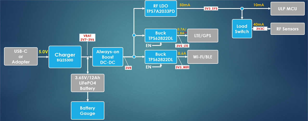
The initial design architecture was based on BQ25300. Since the output is not regulated, a DC-DC boost converter was used as shown in the image below.

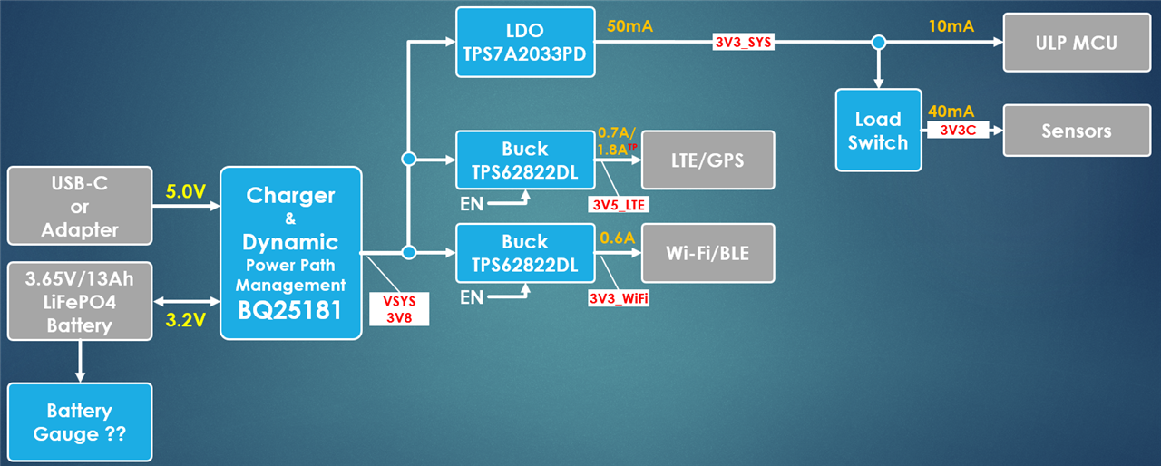
The updated architecture is based on BQ25181. The boost converter was removed since BQ25181 provides regulated output.

1) Please let me know if you agree with the new architecture. 

2) BQ25181 Datasheet indicates "system loads of up to 2.5 A". The IIOT device will have <1A average current with a burst current up to 2A. Is that within the capability of the chip?

3) Given all different charging modes the chip will cycle though, how long does it take to fully charge 10Ah battery?   

4) Any suggestion for LiFePO4 battery gauge?

Thank you

  • Hi,

    1. This architecture looks good. One question, why do you have the connection from the LiFePO4 battery to the BQ25181 labeled with 3.2V when the battery is 3.65V? Are you intentionally limiting the max voltage you will charge the battery? Just curious on the methodology here.

    2. As long as your system load is < 2.5A I don't expect you to run into any issues here.

    3. This is largely dependent on what you select as your charging current. Assuming you are selecting to 1A as your ICHG, I would expect 10-11 Hr from 0-100% SOC. (Around 10Hr for the fast charge portion of the charging cycle plus another 30mins-1Hr for precharge and taper charge.

    4. I would suggest using the BQ34z100-G1 for the gauge here.

    Thanks,

    Jackson

  • 1) 3.2 is the nominal voltage for LiFePO4 Batteries. 3.65 is the end charge voltage. Regarding the battery voltage tracking mode, in case of SYS_REG_CTRL=000, VSYS TARGET = VBAT + 225 mV (3.8 V minimum). Can you please explain whether VSYS will be regulated to 3.8V minimum or VSYS = VBAT + 225mV? For instance, when VBAT = 2.75, what is VSYS? 3V or 3.8V?

    2) Noted.

    3) So the taper charge is 30min~60min. Noted.

    4) Any reason for not considering BQ27Z746 instead of BQ34z100-G1?

    Thanks

  • 1) SYS_REG_CTRL = 000 will have VSYS = 3.8V when VBAT <3.6V. However, once VBAT > 3.6V VSYS will begin tracking the battery so VSYS = VBAT +225mV. That being said, when VBAT = 2.75V, VSYS = 3.8.

    4) The BQ27Z746 should also work. Both devices have the LFP_RELAX feature that is essential when dealing with LiFePO4 cell chemistries to avoid large SOC jumps when relaxing in the flat region of the OCV curve.

    Best Regards,

    Jackson

  • Thank you Jackson... Appreciated.