This thread has been locked.

If you have a related question, please click the "Ask a related question" button in the top right corner. The newly created question will be automatically linked to this question.

TPS2662: damage problem

Part Number: TPS2662

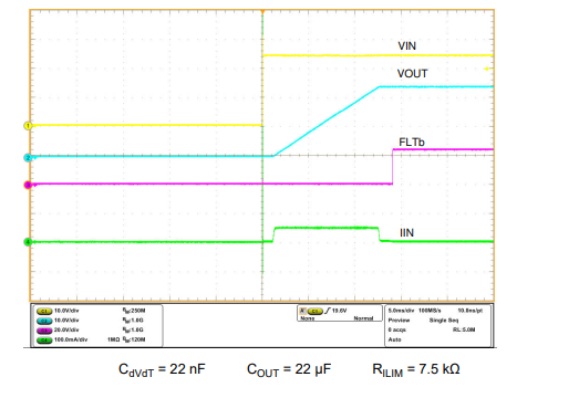
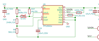
our customer used 24V as our product 's power input, normally it works fine. However, recently, one of our products was damaged according to our customer. we find out it is TPS26625 chip that was damaged in our product. so we want to figure it out why. below is our analyse of that damaged TPS26625 chip.

is there any possibility to cauese this?

1.the damaged chip 's voltage value of each pin when power on.

eFuse Pin Voltage(V)
1、VCC 5
2、Net-(R18-pad2) 3.9
3、Net-(R7-pad2) 0.15
4、SHDN 2.47
5、Net-(C19-pad2) 0
6、GND \
7、Net-(R10-pad2) 0
8、Net-(C19-pad2) 3.98
9、FLT 0
10、VDD 3.22

2. I read from the manual that the efuse voltage max is 62V. Excuse me, the instantaneous high voltage (greater than 62V, such as static electricity) should not burn the chip, right? Only a constant voltage input exceeding 62V will burn out the chip.

  • Hi Chen,

    Even a transient voltage exceeding ABS max voltage can damage the chip.

    Can you share the schematic and impedance of each pin measured with respect to RTN pin of the TPS26625 

    Best Regards,

    Rakesh

  • HI Rakesh,

    This is the schematic,please check .


    This is the RTN pin of the TPS26625 measures the impedance of each pin. Howere , When I tested the impedance, I found that the value was constantly changing, so I intercepted the maximum and minimum values to record.

    eFuse Pin                                Voltage(V)
    1、VCC                                  4.76 ~ 5.06
    2、Net-(R18-pad2)                 3.86 ~ 3.9
    3、Net-(R7-pad2)                   0.14 ~ 0.15
    4、SHDN                                    2.46
    5、Net-(C19-pad2)                       \
    6、GND                                         0
    7、Net-(R10-pad2)                        0
    8、Net-(C19-pad2)                 0 ~ 3.97
    9、FLT                                          0
    10、VDD                                0.27 ~ 3.2

    Thank for your help.

    Best Regards,

    Chen

  • Hi Chen,

    Thanks for info.  I will get back before friday EOD on this.

    Regards

    Kunal Goel

  • Hi Chen,

    Data you shared is voltage values. Please share impedance values for pins with respect to RTN pin when device is unpowered. Also please help with below things:

    1. Is R18 populated or not?

    2. What is input voltage?

    3. Is there some load connected like resistive or eLoad at efuse output during testing?

    4. Is some damage visible on IC?

    5. Please share a startup waveform like this and probe VIN,VOUT,IIN,UVLO:

    Also please share a waveform in running mode of oscilloscope.

    6. Pin impedances when device is off.

    7. did device fail on first power up?

    Regards

    Kunal Goel

  • Hi Kunal Goel,

    Sorry for replying so late.

    1. Is R18 populated or not?
         Not populated.


    2. What is input voltage?
         5V.


    3. Is there some load connected like resistive or eLoad at efuse output during testing?
        A DCDC chip is connected behind the efuse, and then the DCDC chip works for several chips behind

    4. Is some damage visible on IC?
         No visible damage.

    5. Please share a startup waveform like this and probe VIN,VOUT,IIN,UVLO:  Also please share a waveform in running mode of oscilloscope.

        Sorry to tell you, I'm still finding out how to measure IIN. I will tell you the data I have measured now.

        Running_VIN :


        Running_VOUT:

         Running_UVLO:

         StartUp_VIN:

         StartUp_VOUT:

         StartUp_UVLO: 

    6.Pin impedances when device is off.

       I found that the value of pins 6, 9, 10 is constantly increasing.

    eFuse Pin impedance(
    1、VCC 1.1
    2、Net-(R18-pad2) 2.2
    3、Net-(R7-pad2) 0
    4、SHDN 1
    5、Net-(C19-pad2) \
    6、GND 11.1
    7、Net-(R10-pad2) 0
    8、Net-(C19-pad2) 28.3
    9、FLT 11.1
    10、VDD 11.1

    7. did device fail on first power up?
        There is no abnormality in the first use, but it is damaged by the customer during use.

    Thank for your help.

    Best Regards,

    Chen

  • Hi Chen,

    Waveforms are actually not clear to understand. Some suggestions:

    1. On removing R18, device UVLO pin is directly pulled to VIN which can be a concern. UVLO recommended max voltage is 4V, if you apply 5V at VIN it may cause some issue.  Did customer used device with higher VIN than 5V with R18 removed?

    3. Also if customer replace device then it works fine?

    Regards

    Kunal Goel

  • Hi, Kunal Goel

    1. I rechecked the circuit diagram and I found that even with R18 removed, the device UVLO does not pull to VIN.

    2. Yes, when the customer replaces the device, then it works fine

    Thank for your help.

    Best Regards,

    Chen

  • Hi Tong,

    With R18 removed, UVLO is pulled to VIN though R37, right?

    Regards

    Kunal Goel

  • Hi, Kunal Goel

    Sorry, I meant that UVLO is not directly connected to VIN, just through R37.
    In addition, the specification states that if the UVLO pin is not used, connect a 1M resistor to the VIN pin.

    Thank for your help.

    Best Regards,

    Chen

  • Hi Chen,

    Agree with you , 1M pullup may not be a problem. Can customer try to replicate behavior? Do they know test condition after which device failed?

    Regards

    Kunal Goel

  • Hi, Kunal Goel

    So far, there is no other news of efuse broken. I will consult with the client about the test conditions.

    Thank for your help.

    Best Regards,

    Chen

  • Hi, Kunal Goel

    The customer test conditions are as follows
    Power supply: 48V to 24V.
    Situation: Abnormality is suddenly found after a period of normal use.
    Installation location: no high-power electrical appliances nearby.

    I will try to break efuse according to customer conditions

    Can I send you efuse to help analyze the problem?

    Thank for your help.

    Best Regards,

    Chen

  • Hi Chen,

    You can submit return request here for failure analysis of part: https://www.ti.com/productreturns/docs/createReturn.tsp

    Regards

    Kunal Goel