This thread has been locked.

If you have a related question, please click the "Ask a related question" button in the top right corner. The newly created question will be automatically linked to this question.

TLE4275-Q1: how to test the ESR?

Part Number: TLE4275-Q1

Dear team,

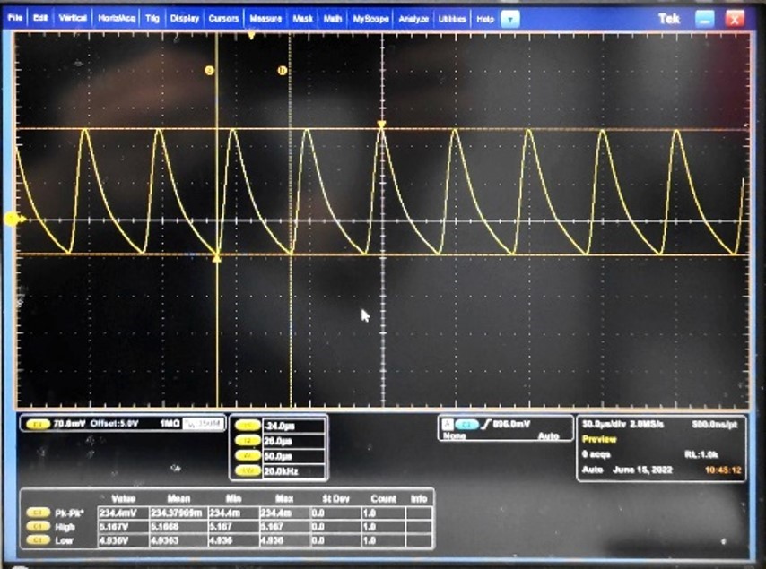
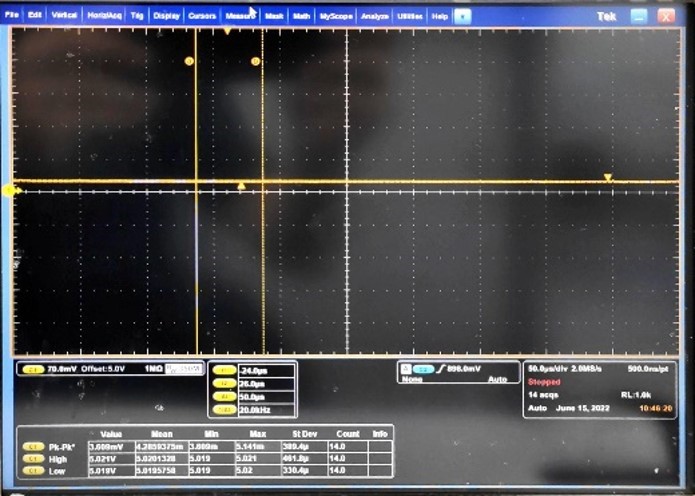
My customer use our TLE4275-Q1, and they found some strange phenomenon. For some chips, the output has 234mV ripple as the second picture. When they remove TLE4275's all load, the ripple disappears.

TLE4275-Q1 has several loads including LDO, resistors and capacitors. It seems that this load will make TLE4275-Q1 unstable. Could you please help provide the debug solution?

with load
without load
In addition, there is a ESR vs load capacitor waveform in our datasheet. Could you please tell me how to test the ESR? My customer test the resistance between OUT pin and GND pin directly. And they found that the resistance is 1ohm when all load is connected; and resistance is 2ohm when they disconnected all load. Is this test method correct? If so, my customer is also considering the ripple is related with the ESR.

Thanks & Best Regards,

Sherry

  • Hey Sherry,

    If the LDO is stable with the output caps and output resistor, the ripple may be caused by the load. What does the load look like?

    The ESR should be found by doing an impedance measurement.

    Thanks,

    -Jimmy

  • Hi Jimmy,

    Thanks for your reply!

    Yes, the ripple seems to be related to load, but we don't understand why the load will impact the chip's stability. Their load is complicated, I didn't get the detailed schematic.

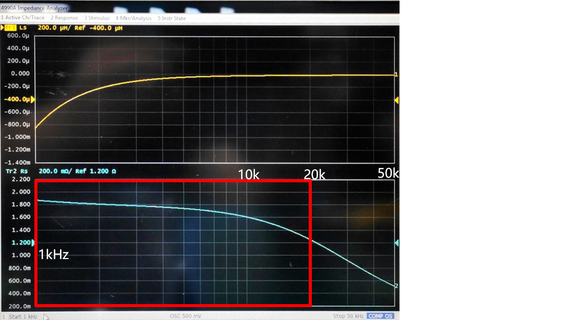
    Before they tried to test the system load's ESR as below. The test method is that, firstly they removed TLE4275 chip from the board; secondly test the resistance between pin5/OUT and pin3/GND. They also tried to keep the chip on the board, and they got the similar result with below. Could you please help check whether this test method is correct? If not, could you please tell me the correct test method?

    When they disconnected their system load and add a 100ohm resistor in parallel with a 10uF capacitor as load, and the 10uF cap is connected in series with a resistor, and the resistor is around 2ohm. They can also reproduce the output faulty ripple. At the same time, the output ESR is 1.02ohm@20kHz. When they removed the load, the output ESR is 2ohm@20kHz, and no faulty ripple.

    Thanks & Best Regards,

    Sherry

  • Hey Sherry,

    It looks like they are measuring the devices output impedance across frequency so it seems like they are doing it right. 

    The load might be dropping the ESR too low and out of the stable ESR Range. What is the function of R4501 on the output? Is this a resistor? If so could they try to check stability with and without the load if this is removed?

    If not, could the 2ohm series resistor in the new load be increased to 3ohms or 4ohms?

    Also could the scope shot be taken from 1 or 10Hz start and up to 100kHz or 1MHz for the full impedance picture?

    Thanks,

    -Jimmy 

  • Hi Jimmy,

    If they removed R4501, the stability is bad because the ESR will be small which will not meet our requirement, so it is our suggest to add R4501 to increase the output ESR.

    I didn't say the background before. Only some devices has problems, and the fault phenomenon follows our chip by ABA test, but ATE test is ok, so the quality team think it is related to customer's system. But our test results proves the fault chip has higher requirement for output ESR.

    I will send you email for this case.

    Thanks & Best Regards,

    Sherry

  • Hey Sherry,

    Thanks for the clarification on R4501. I will close this thread and respond to your email.

    Thanks,

    -Jimmy