This thread has been locked.

If you have a related question, please click the "Ask a related question" button in the top right corner. The newly created question will be automatically linked to this question.

BQ28Z610: Correct steps to get everything ready to run

Part Number: BQ28Z610
Other Parts Discussed in Thread: BQ25883, EV2400, , BQSTUDIO, BQMTESTER

Hello E2E-Community members,

My board has an BQ25883 + BQ28Z610, and I'm using an EV2400 to access them with Battery Management Studio v1.3.101 Build 1.
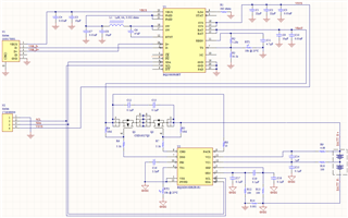
This is my circuit:

After I assemble the board using brand new ICs, these are the steps I'm taking:

A) Placing the 2x NCR18650B batteries on the circuit.

B) Plugging EV2400 to the board and connecting to BQ28Z610 using bqStudio.

C) Once connected, I click on "Chemistry", select the NCR18650B battery, and click "Program Selected Chemistry".

D) Then I click on "Calibration" and perform a Voltage Calibration.


Now I assume the next step is to perform a Current Calibration. The EVM users guide for the BQ28Z610 tells to apply 2A across the 0.001 ohms resistor (R14 in my circuit), type -2000 on the Applied Current box, check "Calibrate Current" and click "Calibrate Gas Gauge".

Questions:

1) Does the current has to be 2A for the current calibration? Can I apply any other current across the 0.001 ohms resistor, such as 550mA, and enter -550 on "Applied Current"?

2) Should I perform the current calibration with the batteries connected to the board? (I assume yes, but just to make sure)

3) Am I doing this correctly so far? Do I need to set any registers or do anything else besides the learning cycle that goes next?

Thanks in advance

  • Hello Eduardo,

    1. The higher the current, the better the accuracy during calibration. We recommend using 2A

    2. All calibration must be performed using stable mV / mA accuracy power supplies. After calibration, program the golden image. (If you are yet to perform learning, then program chemistry and set data memory at this stage.) Then you can attach cells.

    3. Do learning and then verify accuracy.

  • Hello Shirish,

    I'm kinda lost on some things you said on step 2:

    1) About the golden image, this is my very first attempt on designing a battery system. We haven't created a golden file before, nor ever done a learning cycle. So how do we proceed about the golden image? Perform one learning cycle first and do all other procedures before we create a golden file?

    2) So just to confirm, we only attach the NCR18650B battery cells into the circuit board after voltage/current calibration, chemistry programming and setting the data memory? If yes, I assume that we then power the BQ28Z610 for all of those steps using the charger voltage, in our case the 5V from the USB port?

  • Hello Eduardo,

    This is a good reference https://www.ti.com/lit/pdf/slua777

    After you have completed the learning cycle, then you can read out the golden image

    Calibration will require precision power supplies, therefore a charger will not work. Power for programming can come from charger.

  • Hello Shirish,

    Believe me, I've read this. Also watched the video https://www.youtube.com/watch?v=WAcxrGDb68g and read the https://www.ti.com/lit/an/slua903/slua903.pdf?ts=1655100383319 . But it don't say certain basic things that makes first-timers unsure and confused.

    But definitelly your instructions cleared a lot of doubts, thanks very much.

    I will then:

    - Program Chemistry ID and Data Memory.

    - Try my best to build a stable/precise 5V supply using voltage regulators, capacitors and another battery to power the board and perform Current Calibration.

    - Remove the batteries from my board and power it using the stable/precise 5V power supply.

    - Build a 2A stable current drain using a transistor, supplying current for it with another stable power supply, and perform Current Calibration using it.

    - Put the batteries back into the board and perform Voltage Calibration.

    - Perform the Learning Cycle.

    - Save Golden File.

  • Hello Eduardo,

    It is good that some of your doubts have been cleared.

    I don't know if it is worth building a voltage and current source. We normally use calibrated Sourcemeters. If you don't have it, then voltage calibration can be done with a battery, just make sure that there is zero current for a few hours before you try to calibrate with the measured stable voltage. The voltage measured (externally)should not have changed during/after calibration.

    For a current source/sink, you really need equipment. Something like bqMTester may be the next best alternative.

  • Hello Shirish,

    This bqMTester requires the EV2300. We have the EV2400. Also it costs $299, just to perform the Current Calibration step? 

    Then for the Learning Cycle, will it require any other device?

    What would be the result of simple measuring the voltages with a multimeter for the Voltage Calibration, and the current with an amp meter for the Current Calibration? Will it simply result on a small deviation on the Relative State Of Charge value (registers 0x2C/2D)?

  • Hello Eduardo,

    If you choose to skip calibration, then  you may see errors in State of charge and errors in reporting of voltage/current. It is better to skip calibration if you don't have the right equipment.

    We recommend a setup of similar or better accuracy than bqMTester. I provided the link because it has the schematic which could be useful since you said you were going to build something on your own. All you need is a stable current source (1mA accuracy) and stable voltage source(1mV accuracy). The multimeter that is used must be calibrated to standard references. The learning cycle will require a load that can keep the current within specified limits.