This thread has been locked.

If you have a related question, please click the "Ask a related question" button in the top right corner. The newly created question will be automatically linked to this question.

Problem with power supply design with TPS63031 and TPS3619-33

Other Parts Discussed in Thread: TPS3619, TPS63031

Hi!

Below you can see my design for a power supply module.

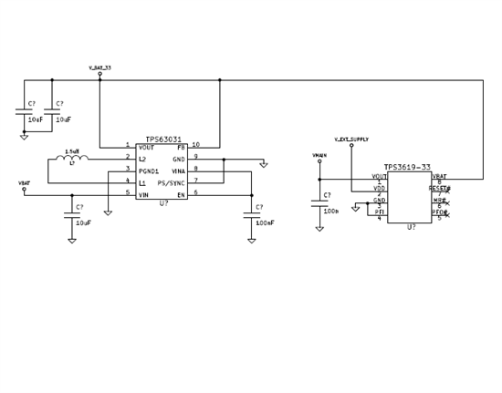
There are two possible input supply voltages : (1)V_EXT_SUPPLY and (2)VBAT. The (1) is supposed to be a regulated voltage of 3.3V and the VBAT comes from an Li-ion battery, ranging from 2.6V to 3.7V.

  • When the V_EXT_SUPPLY is active, the system takes supply power from there. V_EXT_SUPPLY is driven directly through TPS3619 to the rest of the PCB.
  • When the V_EXT_SUPPLY is not present, the system takes supply power from the battery. The battery voltage passes through TPS63031 to be regulated at 3.3V and then through TPS3619 to the rest of the PCB.

VMAIN is connected to various ICs, like a flash memory, a ZigBee module (EM250), supply voltage switches etc.

When operated from the V_EXT_SUPPLY (@ 3.3V), everything is ok.

However, I have some problems with the second option. The supply module does not work properly when VBAT is below ~4.7V (For test purposes I am using a variable lab voltage supply). At the range of around 4.7V to 5.2V TPS63031 produces a regulated voltage @3.3V which is shown below.

4454.PRINT_17.TIF

When I put on a voltage below 4.7V at the input, the VOUT at the TPS63031 is like in picture below.

7823.PRINT_19.TIF

The Picture below shows the transition between 4.7V and some other voltage below that, where the circuit seems not to be working properly.

0184.PRINT_18.TIF

The input voltage, coming from the lab's power supply is shown below during the transition between the correct and the failing operation mode.

4426.PRINT_20.TIF

Can anyone please give me a hint on what could probably be going on here? How could I proceed to debug the situation further and find a solution?


Thanks a lot,

Nikos

  • Your schematic looks ok but your waveforms are unexpected.  Particularly, the picture of Vin in the last picture.

    Could you post your board layout?  How long is the cable from your power supply to the board?  Could you try adding more input capacitance to the board--say 100uF?

    You need to have a steady input source.

  • Yes for sure I will try and put a larger capacitance to the board. I just tried to stick to the recommended schematic from the datasheet of the device.

    Regarding the layout... I do not have it right now with me, but I will try to find it tomorrow or the day after tomorrow. What exactly do you want to see? What plays the most important role? I think that it is implemented in more than one layers.

    Concerning the Vin, I have to add two comments:

    (1)The lab's power supply is obviously a switching power supply. That's why it has that particular image. I will post tomorrow an image of the power supply without being connected on the board. Most probably it will have more or less the same image. But what else could I have done? The battery voltage solution (see (2) below) was not successful, too. The power supply cables are no longer than 10-15cm.

    (2)I have also tried to supply the board with two AA Li-ion batteries in parallel, providing an open voltage of around 3.6V. That voltage is for sure must more stabilized than that of the lab's voltage supply. However, upon connecting the batteries at the board, their voltage falls to around 1.8V and the TPS63031 cannot produce an output voltage of 3.3V.

    Is there any chance that there is a problem with the "cooperation" between the TPS63031 and the TPS3619? Don't know exactly the reason, just guessing. However, I had also used the same connection between the two ICs in another PCB without any problems at that case.

  • The added input capacitance will only help things and may be necessary in this test environment where their are inductive wires connecting the power supply to the IC.  It should not be required in the final application where the battery is presumably right next to the IC.

    On the layout, the input and output capacitors need to be right next to the IC.  The layout should follow the EVM as close as possible.  Poor layout can cause noise and coupling that could result in behavior that you are seeing.  To rule out a layout issue, you can order the EVM and connect it with your same test setup and see if the same issue occurs.

    You lab supply connections sound ok, but no lab supply supply should have the hundreds of mV of ripple on its output that I see in your picture.  But since you tried with a battery and got the same result, we can rule out a poor input source as the cause of the problem.

    The battery voltage should only be drawn down if there is too much load on them.  Do you have a load on the output during this testing?

    Could you provide the part number for your inductor to make sure that it is not saturating?

    The TPS63031 should be able to be used with the TPS3619.  Can you test your circuit with nothing connected to the TPS63031?

  • Chris Glaser said:

    On the layout, the input and output capacitors need to be right next to the IC.  The layout should follow the EVM as close as possible.  Poor layout can cause noise and coupling that could result in behavior that you are seeing.  To rule out a layout issue, you can order the EVM and connect it with your same test setup and see if the same issue occurs.

    Regarding the layout, I will try to post something later this week, since my colleague responsible for the PCB layout is on vacation. However I'm afraid that the layout of the EVM has not been followed in detail. Only the general idea.

     What I can do now is to attach a photo of the PCB showing details of the area around the regulator. U18 is TPS63031, U17 below the inductor is the TPS3619, C42 to the left of C65 is one of the two output capacitors (the other one is on the back side of the PCB) and C40 is the input capacitor.

    Do you think that a wrong layout could cause problems like that?

    Chris Glaser said:

    You lab supply connections sound ok, but no lab supply supply should have the hundreds of mV of ripple on its output that I see in your picture.  But since you tried with a battery and got the same result, we can rule out a poor input source as the cause of the problem.

    You mean the ripple before the regulator stopped working or afterwards?

    Chris Glaser said:

    The battery voltage should only be drawn down if there is too much load on them.  Do you have a load on the output during this testing?

    Well, I forgot to say that the current drawn that seems to be drawn by the circuit during testing at an input voltage of ~5V is around 120mA. However, when I reduce the input voltage, from the point that the regulator stops working, the current drawn fluctuates a lot but is around 400 and even 800mA. And a slight "buzz" can be heard... presumably from the inductor.

    During testing, I do not have any additional load except for the ICs that are on the PCB. As I said, mainly there is a flash memory, an FTDI IC and a microcontroller-ZigBee module. Normally it shouldn't be drawn so much current. For example, when I connect the V_EXT_SUPPLY to 3.3V and the board uses this supply voltage the current drawn is not above around 30mA.

    Chris Glaser said:

    Could you provide the part number for your inductor to make sure that it is not saturating?

    The part number of the inductor that is used is : VLF4012AT-1R5M1R6

    Chris Glaser said:

    The TPS63031 should be able to be used with the TPS3619.  Can you test your circuit with nothing connected to the TPS63031?

    What do you mean with "nothing connected to the TPS63031"? What I can do for sure is to take a spare PCB and populate only the components concerning the TPS63031, without the TPS3619 or any other load. But this will not reproduce the case, since there will be no load at all at the output of the regulator. Moreover, I have used the same schematic on another board and no problems where shown there. Only the layout was slightly different.

  • Yes, you have a non-ideal layout.  Both the input and output capacitors are far from the IC.  This can cause the problem you are seeing.

    I recommend that you order the EVM and wire it into your circuit with your passive components.  This will confirm that your layout is the root cause since the layout of the EVM is known to be good.

    Your inductor looks fine.

    What I meant was to test the TPS63031 part of the circuit separate from anything else.  This would help isolate the problem.  You could build up a new board with just the TPS^3031 and its components on it and I would expect the same issue that you are seeing.  Why do you say that this will not reproduce it?

  • Chris Glaser said:

    Yes, you have a non-ideal layout.  Both the input and output capacitors are far from the IC.  This can cause the problem you are seeing.

    I recommend that you order the EVM and wire it into your circuit with your passive components.  This will confirm that your layout is the root cause since the layout of the EVM is known to be good.

    So to your opinion the layout is the reason for the problem I am facing. I didn't completely understand your recommendation, though. You said that I should use the EVM and wire it into my circuit. What do you mean exactly? To connect the output of the EVM to the V_BAT_33 of  my circuit (see the schematic in my first post), after having removed the on-board TPS63031 and its passives? This would indeed prove that the layout is the root cause or not.

    Chris Glaser said:

    What I meant was to test the TPS63031 part of the circuit separate from anything else.  This would help isolate the problem.  You could build up a new board with just the TPS^3031 and its components on it and I would expect the same issue that you are seeing.  Why do you say that this will not reproduce it?

    What I meant is this: I have a feeling that although this poor layout, if the load at the output of the regulator were different (lower perhaps) there might not be such a problem. That's why I said that by testing the TPS63031 part only of the circuit, without any load, might not reproduce the real problem. Is anything like that possible? That the load current required is too big for the regulator?

    But anyway, since you think that this is not possible, I will try your recommended test and when I have any news I will post again.

    Thanks for the support so far!

  • Yep, that's it.  Just remove the existing TPS63031 on your board and wire the output of the EVM onto your board and see.

    You are correct that a lower load may affect the issue.  But the best path forward is to test with the EVM and see if this helps.